ABB 1SDA067460R1 Moulded Case Breaker - XT1 (IEC60947-2)
Part Number: 1SDA067460R1
Quick Summary
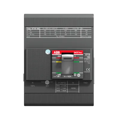
ABB 1SDA067460R1 is a four-pole molded case circuit breaker for protecting low-voltage power distribution. Engineers often face nuisance trips and cramped wiring in compact panels, which this XT1 design helps mitigate with robust mechanical fit and reliable release. The device supports IEC 60947-2 conformance and CE conformity, with GL and LR certifications that bolster global installation confidence. By combining front-terminal accessibility, a clear 70–100 A setting range, and a 690 V class rating, this MCCB delivers predictable protection while enabling scalable, cost-effective panel design across industrial facilities.
Product Information
Extended Description
1SDA067460R1 ABB: C.BREAKER TMAX XT1H 160 FIXED FOUR-POLE WITH FRONT TERMINALS AND THERMOMAGNETIC RELEASE TMD R 100-1000 A
ABB EcoSolutions
Yes
ABB Site Meeting Group Waste To Landfill Target
UL 2799 Zero Waste To Landfill Validation available
End Of Life Disassembling Instructions
Disassembly instructions Tmax XT XT1
Environmental Product Declaration - EPD
EPD Tmax XT XT1 (IT) | EPD Tmax XT XT1 (CN)
Recyclability Rate of the Product acc. to EN45555
Design for Closing Resource Loops - Standard EN45555 - 55.9 %
REACH Declaration
REACh Declaration ABB Sace circuit breakers
RoHS Information
RoHS Declaration ABB Sace circuit breakers
RoHS Status
Following EU Directive 2011/65/EU and Amendment 2015/863 July 22, 2019
Conflict Minerals Reporting Template (CMRT)
CMRT - Conflict Minerals Reporting Template
Toxic Substances Control Act - TSCA
Toxic Substances Control Act (TSCA) declaration
Environmental Information
Breakers - Packaging disposal information
Order Code US and Canada
XT1HE4100AFF000XXX
E-Number (Norway)
4379249
EAN
8015644695224
Minimum Order Quantity
1 piece
Customs Tariff Number
85362090
Product Net Width
101.6 mm
Product Net Height
130 mm
Product Net Depth / Length
70 mm
Product Net Weight
1.4 kg
Package Level 1 Units
box 1 piece
Package Level 1 Width
128 mm
Package Level 1 Height
135 mm
Package Level 1 Depth / Length
143 mm
Package Level 1 Gross Weight
1.44 kg
Package Level 1 EAN
8015644695224
Circuit Breaker Type to be Associated
Power Distribution
Product Main Type
SACE Tmax XT
Product Name
Moulded Case Circuit Breaker
Product Type
Automatic Circuit Breaker
Version
F
CAD Dimensional Drawing
XT1 4p FIXED F
Connecting Capacity Main Circuit
Busbar 45.5 ... 80 mm²
Current Type
AC/DC
Electrical Durability
120 cycles per hour | 8000 cycle
Mechanical Durability
240 cycles per hour | 25000 cycle
Number of Poles
4P
Opening Time
CB with SOR 30 ms | CB with UVR 30 ms
Order Multiple
1 piece
Power Loss
at Rated Operating Conditions per Pole 7 W
Rated Current (In)
100 A
Rated Frequency (f)
50 / 60 Hz
Rated Impulse Withstand Voltage (Uimp)
8 kV
Rated Instantaneous Short-Circuit Current Setting (Ii)
1000 A
Rated Insulation Voltage (Ui)
800 V
Rated Operational Voltage
690 V AC | 500 V DC
Rated Service Short-Circuit Breaking Capacity (Ics)
(220 V AC) 80 kA | (230 V AC) 80 kA | (240 V AC) 80 kA | (380 V AC) 52.5 kA | (415 V AC) 37.5 kA | (440 V AC) 32.5 kA | (500 V AC) 25 kA | (525 V AC) 17.5 kA | (690 V AC) 5 kA | (250 V DC) 2 Poles in Series 52.5 kA | (500 V DC) 3 Poles in Series 52.5 kA
Rated Ultimate Short-Circuit Breaking Capacity (Icu)
(220 V AC) 100 kA | (230 V AC) 100 kA | (240 V AC) 100 kA | (380 V AC) 70 kA | (415 V AC) 70 kA | (440 V AC) 65 kA | (500 V AC) 50 kA | (525 V AC) 35 kA | (690 V AC) 10 kA | (250 V DC) 2 Poles in Series 70 kA | (500 V DC) 3 Poles in Series 70 kA
Rated Uninterrupted Current (Iu)
160 A
Rated Voltage (Ur)
690 V
Recommended Screw Driver
Main Circuit M6
Release
TMD
Release Type
TM
Setting Range
70...100 A
Short-Circuit Performance Level
H
Standards
IEC60947-2
Sub-type
XT1
Terminal Connection Type
Front
Terminal Type
Bolt
Tightening Torque
6 N·m
ATEX Certificate
No certification needed
Data Sheet, Technical Information
SACE Tmax XT IEC Low voltage molded case circuit-breakers Catalog | SACE Tmax XT IEC TECHNICAL CHARACTERISTICS Low voltage molded case circuit-breakers
Declaration of Conformity - CE
EC Declaration of Conformity Tmax XT1
GL Certificate
1SDL000163R0103
LR Certificate
LRs certificate Tmax XT
UL Certificate
No certification needed
VDE Certificate
No certification needed
Dimension Diagram
XT1 3p-4p fixed front terminals
Mechanical Drawings
XT1 3p-4p fixed front terminals
Wiring Diagram
Circuit diagram for XT1, XT2, XT3 and XT4
Instructions and Manuals
Installation instructions XT1
ETIM 8
EC000228 - Power circuit-breaker for trafo/generator/installation protection
ETIM 9
EC000228 - Power circuit-breaker for trafo/generator/installation protection
Object Classification Code
Q
UNSPSC
39120000
WEEE Category
5. Small Equipment (No External Dimension More Than 50 cm)
eClass
V11.1 : 27370409
Feature: Four-pole XT1 configuration with front terminals. Business Impact: Enables compact wiring layouts and reduces panel depth, cutting assembly time and improving heat management in crowded switchgear. Application: Power distribution panels in manufacturing lines and data centers benefiting from streamlined wiring. Feature: Thermomagnetic release (TMD). Business Impact: Delivers fast, selective tripping to minimize downstream downtime and protect critical loads. Application: Motor feeders and distribution circuits in automated lines. Feature: Adjustable setting range 70–100 A with rated current 100 A. Business Impact: Visible protection tuning to match load profiles, improving coordination and reducing nuisance trips. Application: Motors, transformers and large lighting circuits in service bays and production rooms. Feature: 690 V rated operational voltage with 800 V insulation rating compatibility. Business Impact: Broadens applicability across European and global installations, enabling single-sourcing for multi-site deployments. Application: Industrial plants with mixed high and medium voltage panels. Feature: Compliance and environmental data (IEC60947-2, CE, EPD, recyclability). Business Impact: Supports regulatory compliance, sustainability reporting, and end-of-life planning, reducing risk and total cost of ownership. Application: Corporate sustainability programs and procurement spec sheets requiring transparent lifecycle data. Feature: Front-terminal design and bolt terminal type with 6 N·m tightening torque. Business Impact: Facilitates rapid field connections and vibration resistance, lowering maintenance time and rework. Application: Retrofit or new-build panel assemblies where secure, durable terminations are essential.
Get a Quick Quote for a ABB 1SDA067460R1
Chat with us on WhatsApp - fast responses guaranteed
Need to speak with someone? We'll call you back within 2 hours during business hours
Interested in ABB 1SDA067460R1?
Enquire Now
FAQs
This model uses front-terminal connections with bolt terminals and a recommended tightening torque of 6 N·m. Connectors are designed for busbar ranges from 45.5 to 80 mm², supporting straightforward wiring in compact switchgear while maintaining secure, vibration-resistant terminations.
Rated current is 100 A with a setting range of 70–100 A. It operates at 690 V rated voltage (UIC 800 V insulation) and supports AC and DC applications. The device offers high short-circuit interrupt capacities, up to 100 kA at lower voltages, and up to 52.5 kA in higher DC configurations, depending on system voltage.
Yes. The four-pole design with TMD release provides rapid, selective tripping, which helps protect motors and drive systems. The 70–100 A setting range allows tuneable protection for motor feeders, improving uptime and reducing nuisance trips in automated lines.
The device complies with IEC 60947-2 and carries CE conformity. It also aligns with GL and LR certification programs, supporting global deployment and traceability across supply chains and compliance audits.
With a robust front-terminal design and a clear lifecycle dossier including EPD and recyclability data, this MCCB supports sustainable procurement. Routine checks should verify torque on terminations and confirm setting integrity within the 70–100 A range to maintain reliable protection over time.