ABB 1SDA074640R1 Moulded Case Circuit Breaker - UL/CSA
Part Number: 1SDA074640R1
Quick Summary
ABB 1SDA074640R1 Moulded Case Circuit Breaker provides robust overcurrent protection for industrial power distribution. Engineers rely on reliable front-terminal access, precise tripping, and straightforward integration with SACE Tmax XT systems. This device is certified to UL489/CSA CS22.2, with CE conformity and RoHS/REACH declarations, supporting regulatory compliance and safer installation. The TMF thermal-magnetic release and fixed three-pole configuration deliver predictable protection for critical loads across varied supply conditions, including 600Y/347 VAC and 500 V DC. By aligning with these standards, the breaker reduces maintenance costs and downtime while enabling faster commissioning and lifecycle management in modern factories. It integrates seamlessly with ABB EcoSolutions, delivering sustainable, compliant power distribution for industrial plants.
Product Information
Extended Description
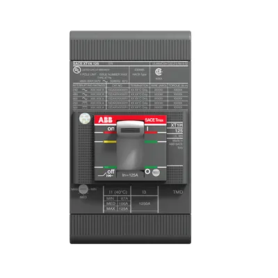
1SDA074640R1 ABB: C.BREAKER TMAX XT1N 125 UL/CSA FIXED THREE-POLE WITH FRONT TERMINALS AND THERMOMAGNETIC RELEASE TMF R 45-500 A
ABB EcoSolutions
Yes
ABB Site Meeting Group Waste To Landfill Target
UL 2799 Zero Waste To Landfill Validation available
End Of Life Disassembling Instructions
Disassembly instructions Tmax XT XT1
Environmental Product Declaration - EPD
EPD Tmax XT XT1 (IT)
Recyclability Rate of the Product acc. to EN45555
Design for Closing Resource Loops - Standard EN45555 - 55.9 %
REACH Declaration
REACh Declaration ABB Sace circuit breakers
RoHS Information
RoHS Declaration ABB Sace circuit breakers
RoHS Status
Following EU Directive 2011/65/EU and Amendment 2015/863 July 22, 2019
Conflict Minerals Reporting Template (CMRT)
CMRT - Conflict Minerals Reporting Template
Toxic Substances Control Act - TSCA
Toxic Substances Control Act (TSCA) declaration
Environmental Information
Breakers - Packaging disposal information
Order Code US and Canada
XT1NU3045AFF000XXX
EAN
8015644785079
Minimum Order Quantity
1 piece
Customs Tariff Number
85362090
Product Net Width
76.2 mm
Product Net Height
130 mm
Product Net Depth / Length
70 mm
Product Net Weight
1.1 kg
Package Level 1 Units
box 1 piece
Package Level 1 Width
128 mm
Package Level 1 Height
135 mm
Package Level 1 Depth / Length
143 mm
Package Level 1 Gross Weight
1.1 kg
Package Level 1 EAN
8015644785079
Circuit Breaker Type to be Associated
Power Distribution
Product Main Type
SACE Tmax XT
Product Name
Moulded Case Circuit Breaker
Product Type
Automatic Circuit Breaker
Suitable for Product Class
SACE Tmax XT
Version
F
CAD Dimensional Drawing
XT1 3p FIXED F
Connecting Capacity Main Circuit
Busbar 45.5 ... 80 mm²
Current Type
AC/DC
Electrical Durability
120 cycles per hour | 8000 cycle
Mechanical Durability
240 cycles per hour | 25000 cycle
Number of Poles
3P
Opening Time
CB with SOR 30 ms | CB with UVR 30 ms
Order Multiple
1 piece
Power Loss
at Rated Operating Conditions per Pole 3 W
Rated Current (In)
45 A
Rated Instantaneous Short-Circuit Current Setting (Ii)
500 A
Rated Operational Voltage
600Y/347 V AC | 500 V DC
Rated Uninterrupted Current (Iu)
125 A
Rated Voltage (Ur)
600Y/347 V
Recommended Screw Driver
Main Circuit M6
Release
TMF
Release Type
TM
Setting Range
50 A
Short-Circuit Performance Level
N
Standards
UL489
Sub-type
XT1
Terminal Connection Type
Front
Terminal Type
Bolt
Tightening Torque
6 N·m
Interrupting Rating acc. to UL489
(240 V AC) 50 kA | (480 V AC) 25 kA | (600Y / 347 V AC) 18 kA | (250 V DC) 2 Poles in Series 35 kA | (500 V DC) 4 Poles in Series Kind 35 kA
ATEX Certificate
No certification needed
CSA Certificate (Intrinsic Safe)
9AKK10103A3905
Data Sheet, Technical Information
SACE Tmax XT UL/CSA Low voltage molded case circuit-breakers UL489 and CSA CS22.2 Standards Catalog | SACE Tmax XT UL/CSA TECHNICAL CHARACTERISTICS Low voltage molded case circuit-breakers for UL489 and CSA CS22.2 Standards
Declaration of Conformity - CE
EC Declaration of Conformity Tmax XT1
UL Certificate
1SDL000163R0111
VDE Certificate
No certification needed
Dimension Diagram
XT1 3p-4p fixed front terminals
Mechanical Drawings
XT1 3p-4p fixed front terminals
Wiring Diagram
Circuit diagram for XT1, XT2, XT3 and XT4
Instructions and Manuals
Installation instructions XT1 UL
ETIM 8
EC000228 - Power circuit-breaker for trafo/generator/installation protection
ETIM 9
EC000228 - Power circuit-breaker for trafo/generator/installation protection
IDEA Granular Category Code (IGCC)
4927 >> Molded case circuit breakers
Object Classification Code
Q
UNSPSC
39121616
WEEE Category
5. Small Equipment (No External Dimension More Than 50 cm)
eClass
V11.1 : 27370409
Feature → Business Impact → Application: 3P front-terminal design enables quick, secure busbar connections with a tightening torque of 6 N·m, reducing field installation time and improving reliability in dense switchgear assemblies. This supports faster commissioning in motor control centers and transformer protection schemes, delivering measurable reductions in install cost and risk. Feature → Application: TMF release provides reliable thermal-magnetic tripping for overload and short-circuit events, minimizing nuisance trips and downtime in high-demand environments such as CNC production lines and packaging facilities. Feature → Business Impact → Application: Rated current of 45 A and rated operational voltage up to 600Y/347 VAC (and 500 V DC) cover typical industrial feeders, enabling safe protection of distribution panels without over-specification. Feature → Application: Front-terminal connection and bolt-type terminals simplify maintenance and retrofits in existing XT frames, improving serviceability and reducing spare-part complexity. Feature → Business Impact → Application: High short-circuit interrupting ratings (UL489) across multiple voltages ensure reliable protection for transformers, generators, and busbar systems, supporting compliance with UL/CSA requirements and reducing downtime during fault conditions. Feature → Application: Mechanical durability of up to 25,000 cycles and electrical durability of up to 8,000 cycles deliver predictable life cycles in continuous production environments, lowering replacement costs and total cost of ownership. Feature → Business Impact → Application: 3P XT1 configuration with fixed front terminals, along with EN45555 and CMRT/REACH/ROHS compliance, supports sustainable end-of-life handling and regulatory reporting, simplifying procurement and environmental responsibilities.
Get a Quick Quote for a ABB 1SDA074640R1
Chat with us on WhatsApp - fast responses guaranteed
Need to speak with someone? We'll call you back within 2 hours during business hours
Interested in ABB 1SDA074640R1?
Enquire Now
FAQs
Install the 3P XT1 breaker with front terminals using the recommended Main Circuit Screwdriver (M6). Tighten to 6 N·m per terminal to ensure a secure, vibration-resistant connection. Follow the XT1 dimensional drawings for mounting clearance and avoid over-bending conductors to maximize reliability in switchgear assemblies.
Key specs include 45 A rated current, rated operational voltage of 600Y/347 VAC or 500 V DC, rated uninterrupted current of 125 A, and a short-circuit instantaneous setting of 500 A. The device is a 3-pole unit with TMF release, designed for front-terminal connections and a 50 A setting range.
Yes. It carries UL489/CSA CS22.2 applicability, with UL Certificate 1SDL000163R0111 and CSA certification 9AKK10103A3905, plus CE Declaration of Conformity. This ensures suitability for UL/CSA compliant electrical protection in industrial facilities.
Interrupting ratings vary by voltage: 240 V AC up to 50 kA, 480 V AC up to 25 kA, and 600Y/347 V AC up to 18 kA. For 250 V DC, 2 poles in series provide 35 kA, and 500 V DC with 4 poles in series also provides 35 kA, ensuring robust protection against high-energy faults.
Expect electrical durability of about 8,000 cycles and mechanical durability up to 25,000 cycles, reducing replacement frequency. The front-terminal design simplifies inspection and replacement, while compliance with RoHS/REACH and end-of-life disassembly instructions support easier maintenance planning and regulatory reporting.