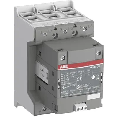
ABB AF116-30-00-32 Contactor - 690 V, 3P, UL/CSA
Part Number: 1SFL427001R3200
Quick Summary
ABB AF116-30-00-32 Contactor is a 3-pole motor control device for industrial equipment. Voltage fluctuations in control circuits often cause nuisance tripping or energy waste. UL/CSA and CE certifications support global compliance, while IP20 coil terminals and standardized dimensions simplify installation. AF technology delivers a wide control voltage range of 48–130 V AC/DC with built-in surge protection, improving reliability in unstable networks. Its compact block design, extendable with auxiliary contact blocks and accessories, reduces panel size and enables scalable machine control—benefiting machine builders and panel shops. This combination translates to faster commissioning, lower wiring costs, and improved energy efficiency.
Product Information
Extended Description
1SFL427001R3200 ABB: The AF116-30-00-32 is a 3 pole - 690 V IEC or 600 V UL contactor with double clamp, controlling motors up to 55 kW / 400 V AC (AC-3) or 75 hp / 480 V UL and switching power circuits up to 160 A (AC-1) or 160 A UL general use. Thanks to the AF technology, the contactor has a wide control voltage range (48-130 V 50/60 Hz and DC), managing large control voltage variations, reducing panel energy consumptions and ensuring distinct operations in unstable networks. Furthermore, surge protection is built-in, offering a compact solution. AF contactors have a block type design, can be easily extended with add-on auxiliary contact blocks and an additional wide range of accessories.
Minimum Order Quantity
1 piece
Customs Tariff Number
8536490099
Data Sheet, Technical Information
1SBC100214C0202 - Main catalog Motor protection and control Manual motor starters, contactors and overload relays (PDF) - Edition 2024
Data Sheet, Technical Information (Part 2)
Contactors and Overload relays guide
Instructions and Manuals
Operating instruction, Contactor, AF(S)116, AF140, AF(S)146
CAD Dimensional Drawing
Information - 2D and 3D files for CAD systems
Product Net Width
90 mm
Product Net Depth / Length
138.5 mm
Product Net Height
150 mm
Product Net Weight
1.55 kg
Number of Main Contacts NO
3
Number of Main Contacts NC
0
Number of Auxiliary Contacts NO
0
Number of Auxiliary Contacts NC
0
Number of Poles
3P
Rated Operational Voltage
Main Circuit 690 V
Rated Frequency (f)
Main Circuit 50 / 60 Hz
Conventional Free-air Thermal Current (Ith)
acc. to IEC 60947-4-1, Open Contactors Θ = 40 °C 160 A
Rated Operational Current AC-1 (Ie)
(690 V) 40 °C 160 A | (690 V) 60 °C 145 A | (690 V) 70 °C 130 A
Rated Operational Current AC-3 (Ie)
(415 V) 60 °C 116 A | (440 V) 60 °C 116 A | (500 V) 60 °C 110 A | (690 V) 60 °C 65 A | (380 / 400 V) 60 °C 116 A | (220 / 230 / 240 V) 60 °C 116 A
Rated Operational Current AC-3e (Ie)
(415 V) 60 °C 116 A | (440 V) 60 °C 116 A | (500 V) 60 °C 110 A | (690 V) 60 °C 65 A | (380 / 400 V) 60 °C 116 A | (220 / 230 / 240 V) 60 °C 116 A
Rated Operational Power AC-3 (Pe)
(400 V) 55 kW | (415 V) 55 kW | (440 V) 75 kW | (500 V) 55 kW | (380 / 400 V) 55 kW | (220 / 230 / 240 V) 30 kW
Rated Operational Power AC-3e (Pe)
(415 V) 55 kW | (440 V) 75 kW | (500 V) 75 kW | (690 V) 55 kW | (380 / 400 V) 55 kW | (220 / 230 / 240 V) 30 kW
Rated Breaking Capacity AC-3
8 x Ie AC-3
Rated Breaking Capacity AC-3e
8.5 x Ie AC-3e
Rated Making Capacity AC-3
10 x Ie AC-3
Rated Making Capacity AC-3e
12 x Ie AC-3e
Rated Short-time Withstand Current Low Voltage (Icw)
at 40 °C Ambient Temp, in Free Air, from a Cold State 10 s 928 A | at 40 °C Ambient Temp, in Free Air, from a Cold State 15 min 160 A | at 40 °C Ambient Temp, in Free Air, from a Cold State 1 min 379 A | at 40 °C Ambient Temp, in Free Air, from a Cold State 1 s 1300 A | at 40 °C Ambient Temp, in Free Air, from a Cold State 30 s 536 A
Maximum Breaking Capacity
cos phi=0.45 (cos phi=0.35 for Ie > 100 A) at 440 V 2000 A | cos phi=0.45 (cos phi=0.35 for Ie > 100 A) at 690 V 1000 A
Rated Insulation Voltage (Ui)
acc. to IEC 60947-4-1 and VDE 0110 (Gr. C) 1000 V | acc. to UL/CSA 1000 V
Rated Impulse Withstand Voltage (Uimp)
Main Circuit 8 kV
Maximum Electrical Switching Frequency
(AC-1) 300 cycles per hour | (AC-2 / AC-4) 150 cycles per hour | (AC-3) 300 cycles per hour
Mechanical Durability
5 million
Maximum Mechanical Switching Frequency
300 cycles per hour
Rated Control Circuit Voltage (Uc)
50 Hz 48 ... 130 V | 60 Hz 48 ... 130 V | DC Operation 48 ... 130 V
Coil Consumption
Holding at Max. Rated Control Circuit Voltage 50 Hz 6 V·A | Holding at Max. Rated Control Circuit Voltage 50 Hz 2 W | Holding at Max. Rated Control Circuit Voltage 60 Hz 6 V·A | Holding at Max. Rated Control Circuit Voltage 60 Hz 2 W | Holding at Max. Rated Control Circuit Voltage DC 2.5 W | Pull-in at Max. Rated Control Circuit Voltage 50 Hz 180 V·A | Pull-in at Max. Rated Control Circuit Voltage 60 Hz 180 V·A | Pull-in at Max. Rated Control Circuit Voltage DC 150 W
Power Loss
at Rated Operating Conditions AC-1 per Pole 12 W | at Rated Operating Conditions AC-3 per Pole 6 W
Operate Time
Between Coil De-energization and NO Contact Opening 40 ... 70 ms | Between Coil Energization and NO Contact Closing 20 ... 55 ms
Connecting Capacity Main Circuit
Flexible 2 x 10 ... 70 mm² | Rigid Cu-Cable 1 x 10 ... 95 mm²
Connecting Capacity Auxiliary Circuit
Flexible with Ferrule 1x 0.75 ... 2.5 mm² | Flexible with Ferrule 2x 0.75 ... 2.5 mm² | Flexible with Insulated Ferrule 1x 0.75 ... 2.5 mm² | Flexible with Insulated Ferrule 2x 0.75 ... 2.5 mm² | Flexible 1x 0.75 ... 2.5 mm² | Flexible 2x 0.75 ... 2.5 mm² | Solid 1x 1 ... 4 mm² | Solid 2x 1 ... 4 mm² | Stranded 1x 1 ... 4 mm² | Stranded 2x 1 ... 4 mm²
Connecting Capacity
Flexible 1 x 10 ... 70 mm² | Flexible 2 x 10 ... 70 mm² | Rigid Cu-Cable 1 x 10 ... 95 mm²
Wire Stripping Length
Auxiliary Circuit 9 mm | Control Circuit 9 mm
Degree of Protection
acc. to IEC 60529, IEC 60947-1, EN 60529 Coil Terminals IP20 | acc. to IEC 60529, IEC 60947-1, EN 60529 Main Terminals IP00
Recommended Screw Driver
Main Circuit M6 | Control Circuit M3.5
Tightening Torque
Auxiliary Circuit 1 N·m | Cable Lug 9 N·m | Control Circuit 1 N·m | Main Circuit 8 N·m
Terminal Type
Double Clamp
Product Name
Block Contactor
Maximum Operating Voltage UL/CSA
Main Circuit 600 V
General Use Rating UL/CSA
(600 V AC) 160 A
Horsepower Rating UL/CSA
(200 ... 208 V AC) Three Phase 30 hp | (220 ... 240 V AC) Three Phase 40 hp | (440 ... 480 V AC) Three Phase 75 hp | (550 ... 600 V AC) Three Phase 100 hp
Tightening Torque UL/CSA
Auxiliary Circuit 9 in·lb | Control Circuit 9 in·lb | Main Circuit 71 in·lb
Full Load Amps Motor Use
(200 ... 208 V AC) Three Phase 92 A | (220 ... 240 V AC) Three Phase 104 A | (440 ... 480 V AC) Three Phase 96 A | (550 ... 600 V AC) Three Phase 99 A
Ambient Air Temperature
Close to Contactor Fitted with Thermal O/L Relay (0.85 ... 1.1 Uc) -25 ... 55 °C | Close to Contactor without Thermal O/L Relay (0.85 ... 1.1 Uc) -40 ... 70 °C | Close to Contactor for Storage -40 ... 70 °C
Maximum Operating Altitude Permissible
Without Derating 3000 m
Conflict Minerals Reporting Template (CMRT)
CMRT - Conflict Minerals Reporting Template
REACH Declaration
REACH - Letter of Confirmation for block contactors, contactor relays, installation contactors, mini contactors, mini contactor relays, thermal overload relays, electronic overload relays and related accessories
RoHS Information
RoHS II declaration for block contactors, installation contactors, mini contactors, mini contactor relays, thermal overload relays, electronic overload relays and related accessories
RoHS Status
Following EU Directive 2011/65/EU and Amendment 2015/863 July 22, 2019
Toxic Substances Control Act - TSCA
Toxic Substances Control Act (TSCA) declaration for Contactors
WEEE B2C / B2B
Business To Business
WEEE Category
5. Small Equipment (No External Dimension More Than 50 cm)
ABB EcoSolutions
Yes
ABB Site Meeting Group Waste To Landfill Target
Non-hazardous waste is sent to a landfill, where there is no alternative option available within 100km of a facility
End Of Life Disassembling Instructions
End-of-life instruction - AF(S)116(B)-**(RT) to AF(S)205(B)-**(RT)
Environmental Product Declaration - EPD
Environmental Product Declaration, AF(S)116-AF(S)146 (SE) Contactors
Improved Energy Efficiency for Customers
Product Efficiency - Product requires less energy to operate compared to similar product on market or older products from the same line
Recyclability Rate of the Product acc. to EN45555
Design for Closing Resource Loops - Standard EN45555 - 87.8 %
Sustainable Material Content in Product (wt. %)
Recycled Metal - 37 %
A2L Certificate – UL
UL Certificate of Compliance A2L, Contactor, AF116 - AF146
Declaration of Conformity - CE
CE Declaration of Conformity - Contactor - AF116...AF370
Declaration of Conformity - UKCA
UK Declaration of Conformity - Contactors >100A
UL Certificate
cULus Certificate, Contactor, AF116-30...AF146-30, AFS116-30...AFS146-30
Package Level 1 Units
box 1 piece
Package Level 1 Width
207 mm
Package Level 1 Depth / Length
216 mm
Package Level 1 Height
150 mm
Package Level 1 Gross Weight
1.75 kg
Package Level 1 EAN
7320500560297
Object Classification Code
Q
ETIM 7
EC000066 - Power contactor, AC switching
ETIM 8
EC000066 - Power contactor, AC switching
ETIM 9
EC000066 - Power contactor, AC switching
eClass
V11.0 : 27371003
UNSPSC
39121529
IDEA Granular Category Code (IGCC)
4758 >> Iec Contactors
AF technology enables a broad control voltage range (48–130 V AC, 48–130 V DC) and built-in surge protection. Business impact: reduces energy waste and improves reliability in voltage-fluctuating environments. Application: control circuits in variable-speed drives and line-start motors. Main circuit rated at 690 V and AC-3 up to 116 A at 690 V, with 55 kW rated power at 400 V. Business impact: supports demanding motor loads with safe switching and extended service life; Application: conveyors, pumps, and machine tools. Certifications including UL/CSA and CE simplify compliant field installations; IP protection (coil IP20, main IP00) enhances safety and serviceability. Business impact: faster regulatory approval and protected operation in harsh industrial settings; Application: generic machine automation panels. Compact dimensions (90 mm wide, 138.5 mm deep, 150 mm high) and double clamp terminals reduce panel space and wiring complexity. Business impact: easier integration and lower installation time; Application: control panels in compact machine lines. Compatibility with add-on auxiliary contact blocks and a wide accessory range supports future expansion; Business impact: scalable solutions that lower total cost of ownership over the lifecycle of equipment; Application: modular motor control systems in evolving automation environments.
Get a Quick Quote for a ABB 1SFL427001R3200
Chat with us on WhatsApp - fast responses guaranteed
Need to speak with someone? We'll call you back within 2 hours during business hours
Interested in ABB 1SFL427001R3200?
Enquire Now
FAQs
When replacing a standard starter, ensure the control wiring matches the coil voltage range (48–130 V AC/DC) and use the double clamp terminals for main and auxiliary circuits. Follow tightening torques: main circuit 8 N·m, auxiliary 1 N·m, and control circuit 1 N·m. Wiring should accommodate flexible 2 x 10–70 mm² or rigid 1 x 10–95 mm² conductors. The device footprint is 90 mm wide, 138.5 mm deep, and 150 mm high, so plan panel space accordingly and consider add-on auxiliary blocks for future expansion.
For AC-3 operation at 60 °C, the AF116-30-00-32 supports 116 A, with rated power up to 55 kW at 400 V and up to 75 kW at higher voltages, depending on supply. It provides a rated breaking capacity of 8 x Ie and a maximum impulse withstand of 8 kV. The device is designed for 690 V main circuit and 50/60 Hz operation, delivering reliable switching for high-inertia motors.
Yes. It carries UL/CSA and CE certifications, supporting regulatory compliance for North American and European installations. This simplifies procurement and reduces external validation time during panel builds. It also aligns with RoHS and REACH requirements, ensuring the product meets environmental and safety standards across global markets.
AF technology provides a wide control voltage range (48–130 V AC/DC) and built-in surge protection, allowing the coil to energize reliably despite control-voltage fluctuations. This reduces nuisance trips, improves machine uptime, and lowers energy consumption by avoiding unnecessary coil energization or misoperation, which is especially valuable in plants with aging electrical infrastructure or inconsistent power quality.
ROI comes from reduced panel energy use due to optimized coil consumption (2 W hold at rated voltage, plus 180 VA pull-in), lower maintenance due to higher mechanical durability (up to 5 million cycles), and fewer commissioning iterations thanks to a compact, extensible design. The AF116-30-00-32 supports scalable control with add-on blocks, enabling future upgrades without replacing the base unit, thereby lowering total cost of ownership.