ABB AF116-30-22-31 Contactor - 690 V UL/CSA 160 A
Part Number: 1SFL427001R3222
Quick Summary
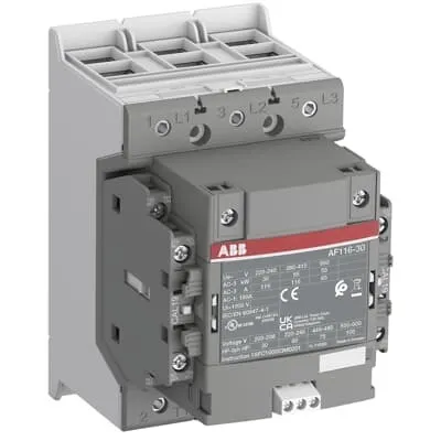
ABB AF116-30-22-31 Contactor is a three-pole motor starter for reliable control of medium to high power drives. In demanding panel environments, a wide control voltage range and built‑in surge protection help reduce nuisance tripping and energy waste. This device carries CE, UKCA and UL/CSA listings with IP20 coil terminals and IP00 main terminals, ensuring broad regulatory compliance. By integrating with add‑on auxiliary blocks and a broad accessories ecosystem, it supports scalable motor protection and simplified maintenance, delivering tangible value for industrial automation and electrical protection projects.
Product Information
Extended Description
1SFL427001R3222 ABB: The AF116-30-22-32 is a 3 pole - 690 V IEC or 600 V UL contactor with double clamp, controlling motors up to 55 kW / 400 V AC (AC-3) or 75 hp / 480 V UL and switching power circuits up to 160 A (AC-1) or 160 A UL general use. Thanks to the AF technology, the contactor has a wide control voltage range (48-130 V 50/60 Hz and DC), managing large control voltage variations, reducing panel energy consumptions and ensuring distinct operations in unstable networks. Furthermore, surge protection is built-in, offering a compact solution. AF contactors have a block type design, can be easily extended with add-on auxiliary contact blocks and an additional wide range of accessories.
Minimum Order Quantity
1 piece
Customs Tariff Number
8536490099
Data Sheet, Technical Information
1SBC100214C0202 - Main catalog Motor protection and control Manual motor starters, contactors and overload relays (PDF) - Edition 2024
Data Sheet, Technical Information (Part 2)
Contactors and Overload relays guide
Instructions and Manuals
Operating instruction, Contactor, AF(S)116, AF140, AF(S)146
CAD Dimensional Drawing
Information - 2D and 3D files for CAD systems
Product Net Width
110 mm
Product Net Depth / Length
138.5 mm
Product Net Height
150 mm
Product Net Weight
1.55 kg
Number of Main Contacts NO
3
Number of Main Contacts NC
0
Number of Auxiliary Contacts NO
2
Number of Auxiliary Contacts NC
2
Number of Poles
3P
Rated Operational Voltage
Main Circuit 690 V
Rated Frequency (f)
Main Circuit 50 / 60 Hz
Conventional Free-air Thermal Current (Ith)
acc. to IEC 60947-4-1, Open Contactors Θ = 40 °C 160 A
Rated Operational Current AC-1 (Ie)
(690 V) 40 °C 160 A | (690 V) 60 °C 145 A | (690 V) 70 °C 130 A
Rated Operational Current AC-3 (Ie)
(415 V) 60 °C 116 A | (440 V) 60 °C 116 A | (500 V) 60 °C 110 A | (690 V) 60 °C 65 A | (380 / 400 V) 60 °C 116 A | (220 / 230 / 240 V) 60 °C 116 A
Rated Operational Current AC-3e (Ie)
(415 V) 60 °C 116 A | (440 V) 60 °C 116 A | (500 V) 60 °C 110 A | (690 V) 60 °C 65 A | (380 / 400 V) 60 °C 116 A | (220 / 230 / 240 V) 60 °C 116 A
Rated Operational Power AC-3 (Pe)
(400 V) 55 kW | (415 V) 55 kW | (440 V) 75 kW | (500 V) 55 kW | (380 / 400 V) 55 kW | (220 / 230 / 240 V) 30 kW
Rated Operational Power AC-3e (Pe)
(415 V) 55 kW | (440 V) 75 kW | (500 V) 75 kW | (690 V) 55 kW | (380 / 400 V) 55 kW | (220 / 230 / 240 V) 30 kW
Rated Breaking Capacity AC-3
8 x Ie AC-3
Rated Breaking Capacity AC-3e
8.5 x Ie AC-3e
Rated Making Capacity AC-3
10 x Ie AC-3
Rated Making Capacity AC-3e
12 x Ie AC-3e
Rated Short-time Withstand Current Low Voltage (Icw)
at 40 °C Ambient Temp, in Free Air, from a Cold State 10 s 928 A | at 40 °C Ambient Temp, in Free Air, from a Cold State 15 min 160 A | at 40 °C Ambient Temp, in Free Air, from a Cold State 1 min 379 A | at 40 °C Ambient Temp, in Free Air, from a Cold State 1 s 1300 A | at 40 °C Ambient Temp, in Free Air, from a Cold State 30 s 536 A
Maximum Breaking Capacity
cos phi=0.45 (cos phi=0.35 for Ie > 100 A) at 440 V 2000 A | cos phi=0.45 (cos phi=0.35 for Ie > 100 A) at 690 V 1000 A
Rated Insulation Voltage (Ui)
acc. to IEC 60947-4-1 and VDE 0110 (Gr. C) 1000 V | acc. to UL/CSA 1000 V
Rated Impulse Withstand Voltage (Uimp)
Main Circuit 8 kV
Maximum Electrical Switching Frequency
(AC-1) 300 cycles per hour | (AC-2 / AC-4) 150 cycles per hour | (AC-3) 300 cycles per hour
Mechanical Durability
5 million
Maximum Mechanical Switching Frequency
300 cycles per hour
Rated Control Circuit Voltage (Uc)
50 Hz 48 ... 130 V | 60 Hz 48 ... 130 V | DC Operation 48 ... 130 V
Coil Consumption
Holding at Max. Rated Control Circuit Voltage 50 Hz 6 V·A | Holding at Max. Rated Control Circuit Voltage 50 Hz 2 W | Holding at Max. Rated Control Circuit Voltage 60 Hz 6 V·A | Holding at Max. Rated Control Circuit Voltage 60 Hz 2 W | Holding at Max. Rated Control Circuit Voltage DC 2.5 W | Pull-in at Max. Rated Control Circuit Voltage 50 Hz 180 V·A | Pull-in at Max. Rated Control Circuit Voltage 60 Hz 180 V·A | Pull-in at Max. Rated Control Circuit Voltage DC 150 W
Power Loss
at Rated Operating Conditions AC-1 per Pole 12 W | at Rated Operating Conditions AC-3 per Pole 6 W
Operate Time
Between Coil De-energization and NO Contact Opening 40 ... 70 ms | Between Coil Energization and NO Contact Closing 20 ... 55 ms
Connecting Capacity Main Circuit
Flexible 2 x 10 ... 70 mm² | Rigid Cu-Cable 1 x 10 ... 95 mm²
Connecting Capacity Auxiliary Circuit
Flexible with Ferrule 1x 0.75 ... 2.5 mm² | Flexible with Ferrule 2x 0.75 ... 2.5 mm² | Flexible with Insulated Ferrule 1x 0.75 ... 2.5 mm² | Flexible with Insulated Ferrule 2x 0.75 ... 2.5 mm² | Flexible 1x 0.75 ... 2.5 mm² | Flexible 2x 0.75 ... 2.5 mm² | Solid 1x 1 ... 4 mm² | Solid 2x 1 ... 4 mm² | Stranded 1x 1 ... 4 mm² | Stranded 2x 1 ... 4 mm²
Connecting Capacity
Flexible 1 x 10 ... 70 mm² | Flexible 2 x 10 ... 70 mm² | Rigid Cu-Cable 1 x 10 ... 95 mm²
Wire Stripping Length
Auxiliary Circuit 9 mm | Control Circuit 9 mm
Degree of Protection
acc. to IEC 60529, IEC 60947-1, EN 60529 Coil Terminals IP20 | acc. to IEC 60529, IEC 60947-1, EN 60529 Main Terminals IP00
Recommended Screw Driver
Main Circuit M6 | Control Circuit M3.5
Tightening Torque
Auxiliary Circuit 1 N·m | Cable Lug 9 N·m | Control Circuit 1 N·m | Main Circuit 8 N·m
Terminal Type
Double Clamp
Product Name
Block Contactor
Maximum Operating Voltage UL/CSA
Main Circuit 600 V
General Use Rating UL/CSA
(600 V AC) 160 A
Horsepower Rating UL/CSA
(200 ... 208 V AC) Three Phase 30 hp | (220 ... 240 V AC) Three Phase 40 hp | (440 ... 480 V AC) Three Phase 75 hp | (550 ... 600 V AC) Three Phase 100 hp
Tightening Torque UL/CSA
Auxiliary Circuit 9 in·lb | Control Circuit 9 in·lb | Main Circuit 71 in·lb
Full Load Amps Motor Use
(200 ... 208 V AC) Three Phase 92 A | (220 ... 240 V AC) Three Phase 104 A | (440 ... 480 V AC) Three Phase 96 A | (550 ... 600 V AC) Three Phase 99 A
Ambient Air Temperature
Close to Contactor Fitted with Thermal O/L Relay (0.85 ... 1.1 Uc) -25 ... 55 °C | Close to Contactor without Thermal O/L Relay (0.85 ... 1.1 Uc) -40 ... 70 °C | Close to Contactor for Storage -40 ... 70 °C
Maximum Operating Altitude Permissible
Without Derating 3000 m
Conflict Minerals Reporting Template (CMRT)
CMRT - Conflict Minerals Reporting Template
REACH Declaration
REACH - Letter of Confirmation for block contactors, contactor relays, installation contactors, mini contactors, mini contactor relays, thermal overload relays, electronic overload relays and related accessories
RoHS Information
RoHS II declaration for block contactors, installation contactors, mini contactors, mini contactor relays, thermal overload relays, electronic overload relays and related accessories
RoHS Status
Following EU Directive 2011/65/EU and Amendment 2015/863 July 22, 2019
Toxic Substances Control Act - TSCA
Toxic Substances Control Act (TSCA) declaration for Contactors
WEEE B2C / B2B
Business To Business
WEEE Category
5. Small Equipment (No External Dimension More Than 50 cm)
ABB EcoSolutions
Yes
ABB Site Meeting Group Waste To Landfill Target
Non-hazardous waste is sent to a landfill, where there is no alternative option available within 100km of a facility
End Of Life Disassembling Instructions
End-of-life instruction - AF(S)116(B)-**(RT) to AF(S)205(B)-**(RT)
Environmental Product Declaration - EPD
Environmental Product Declaration, AF(S)116-AF(S)146 (SE) Contactors
Improved Energy Efficiency for Customers
Product Efficiency - Product requires less energy to operate compared to similar product on market or older products from the same line
Recyclability Rate of the Product acc. to EN45555
Design for Closing Resource Loops - Standard EN45555 - 87.8 %
Sustainable Material Content in Product (wt. %)
Recycled Metal - 37 %
A2L Certificate – UL
UL Certificate of Compliance A2L, Contactor, AF116 - AF146
Declaration of Conformity - CE
CE Declaration of Conformity - Contactor - AF116...AF370
Declaration of Conformity - UKCA
UK Declaration of Conformity - Contactors >100A
UL Certificate
cULus Certificate, Contactor, AF116-30...AF146-30, AFS116-30...AFS146-30
Package Level 1 Units
box 1 piece
Package Level 1 Width
207 mm
Package Level 1 Depth / Length
216 mm
Package Level 1 Height
150 mm
Package Level 1 Gross Weight
1.75 kg
Package Level 1 EAN
7320500560372
Object Classification Code
Q
ETIM 7
EC000066 - Power contactor, AC switching
ETIM 8
EC000066 - Power contactor, AC switching
ETIM 9
EC000066 - Power contactor, AC switching
eClass
V11.0 : 27371003
UNSPSC
39121529
IDEA Granular Category Code (IGCC)
4758 >> Iec Contactors
Feature AF technology provides a wide control voltage range (24–60 V AC, 20–60 V DC), enabling stable operation across fluctuating networks. Business Impact This reduces panel energy consumption and minimizes control power budgeting, which lowers total cost of ownership in automated lines. Application Ideal for panel builders targeting robust motor control with minimal variants, especially where supply variation is common. Feature Built‑in surge protection protects switching circuits from transient spikes, extending contactor life and reducing maintenance downtime. Business Impact Fewer outages, lower replacement costs, and longer component lifetimes in high‑dV/dt environments. Application Suitable for conveyors, presses, and packaging lines where transients are frequent. Feature Block type design with easy extension using auxiliary contact blocks and a wide accessories family. Business Impact Modular, scalable installations with simplified wiring and faster commissioning. Application Retrofit and future expansions in existing control panels without rearranging core hardware. Feature Coil consumption and power loss data (Holding 5.5 V·A/2.5 W at 50 Hz; Pull‑in 225 V·A). Business Impact Lower running energy, cooler panel temperatures, and improved reliability in energy‑sensitive environments. Application Ideal for continuous operation in automotive, food & beverage, and general manufacturing lines. Feature Rated Operational Current AC‑3 up to 116 A at 690 V and AC‑1 up to 160 A; 3P configuration with 3 main NO contacts. Business Impact Strong motor starting capacity and broad voltage compatibility reduce the need for oversize components. Application Suitable for motors up to 55 kW at 400 V and 75 hp at 480 V UL, enabling compact, efficient drives. Feature Double clamp terminals and defined tightening torques (Main 8 N·m, Auxiliary 1 N·m, Control 1 N·m). Business Impact Secure, vibration‑resistant connections with predictable maintenance intervals. Application Critical in high‑vibration panels and serviceable field installations. Feature Comprehensive documentation and CAD drawings, plus access to data sheets and manuals. Business Impact Accelerates design validation, reduces engineering cycles, and supports compliance audits. Application Beneficial for OEMs and system integrators pursuing fast, error‑free installations.
Get a Quick Quote for a ABB 1SFL427001R3222
Chat with us on WhatsApp - fast responses guaranteed
Need to speak with someone? We'll call you back within 2 hours during business hours
Interested in ABB 1SFL427001R3222?
Enquire Now
FAQs
Wiring requires using the Double Clamp terminals for the main circuit and wiring the auxiliary circuits to the NO contacts. Main circuit conductors are 10–70 mm² flexible or 10–95 mm² rigid Cu, with a tightening torque of 8 N·m on the main circuit terminals and 1 N·m on auxiliary/control circuits. Use the 3P configuration for standard three-phase motors and ensure clearance for 690 V operation. For panel layouts, reference the CAD drawings and datasheet with 2 NO auxiliary contacts for coordination with starter relays.
Coil operating limits follow IEC 60947-4-1: 0.85 x Uc minimum to 1.1 x Uc maximum, with a temperature threshold θ ≤ 70 °C. Coil consumption varies by operation: holding at max rated voltage is 5.5 V·A (50 Hz) or 2.5 W (50 Hz/60 Hz), and pull-in at max rated voltage is 225 V·A (50 Hz) or 210 W (DC). These values enable accurate sizing for control circuits and energy budgeting in automation panels.
Yes. The AF116 series is CE and UL/CSA listed, with UKCA declarations and IP protection configurations specified for coil terminals (IP20) and main terminals (IP00). This makes it suitable for European and North American installations in general motor protection and control applications, including panel assemblies, machine building, and process lines that require certified electrical protection components.
Key protections include built-in surge protection, IP20 coil terminals and IP00 main terminals, and rated currents: AC‑1 up to 160 A and AC‑3 up to 116 A at various voltages. It supports motors up to 55 kW (400 V) and 75 hp (440–480 V). Ensure your system meets CE/UKCA/UL requirements and that wiring torque and conductor sizes align with the tightening torques specified (Main 8 N·m, Auxiliary 1 N·m, Control 1 N·m).
The wide control voltage tolerance and surge protection reduce control panel faults and nuisance trips, saving downtime. The compact AF technology enables energy-efficient operation, lowering coil power draw, while the modular add‑on auxiliary blocks simplify future upgrades without major rework. Combined with 5 million mechanical cycles and low maintenance needs, this contactor supports longer service intervals and reduced spare parts inventory.