ABB AF116-30-11B-13 Contactor - CE and UL Certified
Part Number: 1SFL427002R1311
Quick Summary
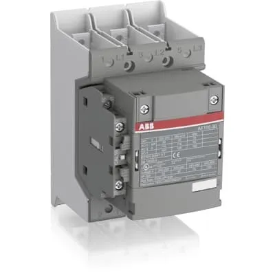
The ABB AF116-30-11B-13 Contactor is a 3-pole block device designed for motor control in industrial drives. It provides reliable switching for motors up to 55 kW at 400 V AC (AC-3) or 75 hp at 480 V UL, with a broad control voltage range to tolerate network fluctuations. In many panel installations, voltage instability can cause nuisance trips and energy waste; AF technology stabilizes performance across 100–250 V AC or DC control signals, reducing downtime and wasted energy. This product carries CE conformity and UL/CSA approvals, supporting global deployments, while built-in surge protection and a compact block design simplify installation. Compatibility with add-on auxiliary contact blocks and a wide accessories range enables scalable, cost-efficient motor protection and control over the product lifetime.
Product Information
Extended Description
1SFL427002R1311 ABB: The AF116-30-11B-13 is a 3 pole - 690 V IEC or 600 V UL contactor with pre-mounted auxiliary contacts and Main Circuit Bars, controlling motors up to 55 kW / 400 V AC (AC-3) or 75 hp / 480 V UL and switching power circuits up to 160 A (AC-1) or 160 A UL general use. Thanks to the AF technology, the contactor has a wide control voltage range (100-250 V 50/60 Hz and DC), managing large control voltage variations, reducing panel energy consumptions and ensuring distinct operations in unstable networks. Furthermore, surge protection is built-in, offering a compact solution. AF contactors have a block type design, can be easily extended with add-on auxiliary contact blocks and an additional wide range of accessories.
Country of Origin
China (CN)
Lead Time
52 day
Made To Order
No
Warranty Return
Product under warranty must be returned
Product Sales Status
Inactive
Quote Only
No
Minimum Order Quantity
1 piece
Customs Tariff Number
85364900
Data Sheet, Technical Information
1SBC100214C0202 - Main catalog Motor protection and control Manual motor starters, contactors and overload relays (PDF) - Edition 2024
Data Sheet, Technical Information (Part 2)
Contactors and Overload relays guide
Instructions and Manuals
Operating instruction, Contactor, AF(S)116, AF140, AF(S)146
CAD Dimensional Drawing
Information - 2D and 3D files for CAD systems
Dimension Diagram
1SFB535001G1051
Product Net Width
90 mm
Product Net Depth / Length
126 mm
Product Net Height
150 mm
Product Net Weight
1.3 kg
Number of Main Contacts NO
3
Number of Main Contacts NC
0
Number of Auxiliary Contacts NO
1
Number of Auxiliary Contacts NC
1
Number of Poles
3P
Rated Operational Voltage
Main Circuit 690 V
Rated Frequency (f)
Main Circuit 50 / 60 Hz
Conventional Free-air Thermal Current (Ith)
acc. to IEC 60947-4-1, Open Contactors Θ = 40 °C 160 A
Rated Operational Current AC-1 (Ie)
(690 V) 40 °C 160 A | (690 V) 60 °C 145 A | (690 V) 70 °C 130 A
Rated Operational Current AC-3 (Ie)
(415 V) 55 °C 116 A | (440 V) 55 °C 116 A | (500 V) 55 °C 110 A | (690 V) 55 °C 65 A | (380 / 400 V) 55 °C 116 A | (220 / 230 / 240 V) 55 °C 116 A
Rated Operational Current AC-3e (Ie)
(415 V) 60 °C 116 A | (440 V) 60 °C 116 A | (500 V) 60 °C 110 A | (690 V) 60 °C 65 A | (380 / 400 V) 60 °C 116 A | (220 / 230 / 240 V) 60 °C 116 A
Rated Operational Current DC-1 (Ie)
(110 V) 2 Poles in Series, 40 °C 145 A | (220 V) 3 Poles in Series, 40 °C 145 A
Rated Operational Current DC-3 (Ie)
(110 V) 2 Poles in Series, 40 °C 145 A | (220 V) 3 Poles in Series, 40 °C 145 A
Rated Operational Current DC-5 (Ie)
(110 V) 2 Poles in Series, 40 °C 145 A | (220 V) 3 Poles in Series, 40 °C 145 A
Rated Operational Power AC-3 (Pe)
(415 V) 55 kW | (440 V) 75 kW | (500 V) 75 kW | (690 V) 55 kW | (380 / 400 V) 55 kW | (220 / 230 / 240 V) 30 kW
Rated Operational Power AC-3e (Pe)
(415 V) 55 kW | (440 V) 75 kW | (500 V) 75 kW | (690 V) 55 kW | (380 / 400 V) 55 kW | (220 / 230 / 240 V) 30 kW
Rated Breaking Capacity AC-3
8 x Ie AC-3
Rated Breaking Capacity AC-3e
8.5 x Ie AC-3e
Rated Making Capacity AC-3
10 x Ie AC-3
Rated Making Capacity AC-3e
12 x Ie AC-3e
Short-Circuit Protective Devices
gG Type Fuses 250 A
Rated Short-time Withstand Current Low Voltage (Icw)
at 40 °C Ambient Temp, in Free Air, from a Cold State 10 s 928 A | at 40 °C Ambient Temp, in Free Air, from a Cold State 15 min 160 A | at 40 °C Ambient Temp, in Free Air, from a Cold State 1 min 379 A | at 40 °C Ambient Temp, in Free Air, from a Cold State 1 s 1160 A | at 40 °C Ambient Temp, in Free Air, from a Cold State 30 s 536 A
Maximum Breaking Capacity
cos phi=0.45 (cos phi=0.35 for Ie > 100 A) at 440 V 2000 A | cos phi=0.45 (cos phi=0.35 for Ie > 100 A) at 690 V 1000 A
Rated Insulation Voltage (Ui)
acc. to IEC 60947-4-1 and VDE 0110 (Gr. C) 1000 V | acc. to UL/CSA 600 V
Rated Impulse Withstand Voltage (Uimp)
Main Circuit 8 kV
Maximum Electrical Switching Frequency
(AC-1) 300 cycles per hour | (AC-2 / AC-4) 150 cycles per hour | (AC-3) 300 cycles per hour
Mechanical Durability
5 million
Maximum Mechanical Switching Frequency
300 cycles per hour
Coil Operating Limits
(acc. to IEC 60947-4-1) 0.85 x Uc Min. ... 1.1 x Uc Max. (at θ ≤ 70 °C)
Rated Control Circuit Voltage (Uc)
50 Hz 100 ... 250 V | 60 Hz 100 ... 250 V | DC Operation 100 ... 250 V
Coil Consumption
Holding at Max. Rated Control Circuit Voltage 50 Hz 6 V·A | Holding at Max. Rated Control Circuit Voltage 60 Hz 6 V·A | Holding at Max. Rated Control Circuit Voltage DC 3 W | Pull-in at Max. Rated Control Circuit Voltage 50 Hz 130 V·A | Pull-in at Max. Rated Control Circuit Voltage 60 Hz 130 V·A | Pull-in at Max. Rated Control Circuit Voltage DC 135 W
Power Loss
at Rated Operating Conditions per Pole 6 W
Operate Time
Between Coil De-energization and NO Contact Opening 37 ... 47 ms | Between Coil Energization and NO Contact Closing 25 ... 55 ms
Connecting Capacity Main Circuit
Flexible 1 x 10 ... 70 mm² | Rigid Cu-Cable 2 x 10 ... 95 mm²
Connecting Capacity Auxiliary Circuit
Flexible with Ferrule 1x 0.75 ... 2.5 mm² | Flexible with Insulated Ferrule 1x 0.75 ... 2.5 mm² | Flexible 2x0.75 ... 2.5 mm² | Solid 2 x 1 ... 4 mm² | Stranded 1 x 1 .... 4 mm²
Connecting Capacity
Flexible 2 x 10 ... 70 mm² | Rigid Cu-Cable 2 x 10 ... 95 mm²
Degree of Protection
acc. to IEC 60529, IEC 60947-1, EN 60529 Coil Terminals IP20 | acc. to IEC 60529, IEC 60947-1, EN 60529 Main Terminals IP00
Tightening Torque
Cable Lug 9 N·m | Main Circuit 8 N·m
Terminal Type
Main Circuit: Bars
Product Name
Block Contactor
Maximum Operating Voltage UL/CSA
Main Circuit 600 V
General Use Rating UL/CSA
(600 V AC) 160 A
Horsepower Rating UL/CSA
(200 V AC) Three Phase 30 hp | (208 V AC) Three Phase 30 hp | (220 ... 240 V AC) Three Phase 40 hp | (440 ... 480 V AC) Three Phase 75 hp | (550 ... 600 V AC) Three Phase 100 hp
Full Load Amps Motor Use
(440 ... 480 V AC) Three Phase 96 A | (550 ... 600 V AC) Three Phase 99 A
Ambient Air Temperature
Close to Contactor Fitted with Thermal O/L Relay (0.85 ... 1.1 Uc) -25 ... 50 °C | Close to Contactor without Thermal O/L Relay (0.85 ... 1.1 Uc) -40 ... 70 °C | Close to Contactor for Storage -40 ... 70 °C
Maximum Operating Altitude Permissible
Without Derating 3000 m
Conflict Minerals Reporting Template (CMRT)
CMRT - Conflict Minerals Reporting Template
REACH Declaration
REACH - Letter of Confirmation for block contactors, contactor relays, installation contactors, mini contactors, mini contactor relays, thermal overload relays, electronic overload relays and related accessories
RoHS Information
RoHS II declaration for block contactors, installation contactors, mini contactors, mini contactor relays, thermal overload relays, electronic overload relays and related accessories
RoHS Status
Following EU Directive 2011/65/EU and Amendment 2015/863 July 22, 2019
Toxic Substances Control Act - TSCA
Toxic Substances Control Act (TSCA) declaration for Contactors
WEEE B2C / B2B
Business To Business
WEEE Category
5. Small Equipment (No External Dimension More Than 50 cm)
ABB EcoSolutions
Yes
ABB Site Meeting Group Waste To Landfill Target
Non-hazardous waste is sent to a landfill, where there is no alternative option available within 100km of a facility
End Of Life Disassembling Instructions
End-of-life instruction - AF(S)116(B)-**(RT) to AF(S)205(B)-**(RT)
Environmental Product Declaration - EPD
Environmental Product Declaration, AF(S)116-AF(S)146 (SE) Contactors
Improved Energy Efficiency for Customers
Product Efficiency - Product requires less energy to operate compared to similar product on market or older products from the same line
Recyclability Rate of the Product acc. to EN45555
Design for Closing Resource Loops - Standard EN45555 - 87.8 %
Sustainable Material Content in Product (wt. %)
Recycled Metal - 37 %
A2L Certificate – UL
UL Certificate of Compliance A2L, Contactor, AF116 - AF146
ABS Certificate
ABS Approval, Contactor, AF116 ... AF370 (Sweden)
BV Certificate
BV Certificate, Contactor, AF116-30 ... AF370-30...AF116-40...AF370-40
CB Certificate
SEMKO_SE-70479M1
CCS Certificate
CCS Certificate, Contactor, AF116 to AF2850 (Sweden)
CQC Certificate
CQC Certificate, AC Contactor, AF116-*-*-*, AF140-*-*-*, AF146-*-*-*, AF116B-*-*-*, AF140B-*-*-*, AF146B-*-*-*, AFS116-30-*-*,AFS140-30-*-*, AFS146-30-*-*, Made in Sweden
Declaration of Conformity - CCC
CCC Declaration of Conformity, AC Contactor, AF116-*-*-*, AF140-*-*-*, AF146-*-*-*, AF116B-*-*-*, AF140B-*-*-*, AF146B-*-*-*, AFS116-30-*-*,AFS140-30-*-*, AFS146-30-*-*, Made in Sweden
Declaration of Conformity - CE
CE Declaration of Conformity - Contactor - AF116...AF370
Declaration of Conformity - UKCA
UK Declaration of Conformity - Contactors >100A
DNV Certificate
DNV-certificate, Contactors, AF116-30...AF370-30 and AF116-40...AF370-40
EAC Certificate
9AKK107046A8618
LR Certificate
Lloyds register Certificate, Contactor, AF116-30 ... AF370-30, AF116-40...AF370-40
PRS Certificate
PRS Certificate - AF116...AF1650
RINA Certificate
RINA Certificate, AF95, AF110, AF145, AF185, AF210, AF260, AF300, AF400, AF460, AF580, AF750, AF1250, AF1350, AF1650, AF2050, AF2650, AF116, AF140, AF146, AF190, AF205, AF265, AF305, AF370
RMRS Certificate
9AKK107045A6978
UL Certificate
cULus Certificate, Contactor, AF116-30...AF146-30, AFS116-30...AFS146-30
UL Listing Card
UL_E36588
Package Level 1 Units
box 1 piece
Package Level 1 Width
207 mm
Package Level 1 Depth / Length
216 mm
Package Level 1 Height
150 mm
Package Level 1 Gross Weight
1.5 kg
Package Level 1 EAN
7320500476475
Object Classification Code
Q
ETIM 7
EC000066 - Power contactor, AC switching
ETIM 8
EC000066 - Power contactor, AC switching
ETIM 9
EC000066 - Power contactor, AC switching
eClass
V11.0 : 27371003
UNSPSC
39121529
IDEA Granular Category Code (IGCC)
4758 >> Iec Contactors
E-Number (Finland)
3706180
E-Number (Norway)
4117615
Feature: Wide control voltage range (100–250 V AC/ DC) enables stable operation in networks with voltage fluctuations. Impact: Reduces nuisance trips and energy waste; Application: Reliable motor control in automotive, packaging, and material handling lines. Feature: AF technology with surge protection delivers robust switching even in unstable grids. Impact: Improves panel reliability and reduces diagnostic time; Application: Medium-to-high power drives where supply quality varies. Feature: Pre-mounted auxiliary contact and block-type design allow quick expansion with add-on contact blocks. Impact: Accelerates installation, lowers wiring errors, and simplifies future upgrades; Application: Modular conveyor and process lines. Feature: Main circuit bars and compact footprint (90 x 126 x 150 mm) enable space-efficient panel layouts. Impact: Frees cabinet space, simplifies routing, and improves cooling efficiency; Application: Control panels in tight electrical rooms. Feature: Rated for 690 V main circuit, AC-3 and AC-1 current ranges, and DC options with compatible UL/CSA and CE certifications. Impact: Broadens applicability across global sites; Application: Motor starters for diverse industrial environments. Feature: IP20 coil terminals and IP00 main terminals support safe operation and straightforward maintenance. Impact: Safer access and reduced risk during installation; Application: Indoor, controlled environments with standard enclosure practices. Feature: Energy-conscious design with low coil consumption (6 W holding, 130 V·A pull-in, 135 W DC pull-in) supports lower running costs. Impact: Improves total cost of ownership and reduces panel heat; Application: Continuous operation in continuous process lines.
Get a Quick Quote for a ABB 1SFL427002R1311
Chat with us on WhatsApp - fast responses guaranteed
Need to speak with someone? We'll call you back within 2 hours during business hours
Interested in ABB 1SFL427002R1311?
Enquire Now
FAQs
Install the AF116-30-11B-13 as a 3-pole block contactor with main circuit bars and pre-mounted auxiliary contacts. Use 90 mm x 126 mm x 150 mm footprint, connect flexible 2 x 10–70 mm² or rigid 2 x 10–95 mm² conductors to the main circuit, torque main lugs at 9 N·m and main circuit terminals at 8 N·m. Ensure coil connections match a 100–250 V control supply. The device supports add-on auxiliary blocks for future expansion.
For AC-3 operation at 690 V, the rated current Ie is 65–116 A depending on ambient temperature (up to 55 °C) and configuration. The unit provides up to 55 kW at 415 V and up to 55 kW at 690 V in AC-3, with AC-1 ratings up to 160 A and 75 hp at higher UL voltages. This makes it suitable for motor starting and protection in diverse industrial applications.
Yes. The AF116-30-11B-13 carries CE conformity and UL/CSA approvals, including UL Certificate and UL_E36588 listing. It supports international installation with compliance documentation, Declaration of Conformity for CE, and country-specific certifications listed in its certificates and declarations. This ensures regulatory alignment for projects across Europe, North America, and other regions.
The contactor uses a block-type design that is easily extended with add-on auxiliary contact blocks. It ships with a 1 NO/1 NC auxiliary contact and pre-mounted auxiliary blocks, allowing straightforward upgrades to increased control functionality. It is compatible with standard cabinet designs and allows quick integration with existing motor protection and control schemes in automated lines.
Coil operating voltage spans 100–250 V at 50/60 Hz or DC operation. Ambient operating range is -25 to 50 °C with a 0.85–1.1 Uc enabling stable operation near rated load with thermal overloads. Coil terminals are IP20 protected, while main terminals are IP00. The device is designed for indoor use up to 3000 m altitude without derating and includes surge protection for robust operation in variable networks.