ABB AF116-30-00B-31 Contactor - AF Technology
Part Number: 1SFL427002R3100
Quick Summary
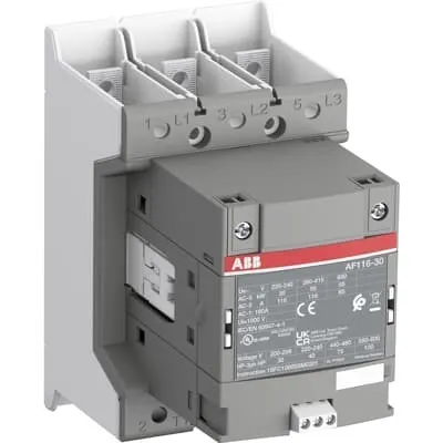
ABB AF116-30-00B-31 Contactor is a three-pole motor starter engineered for reliable control of motors in industrial automation. In challenging environments with voltage fluctuations, conventional starters can trip or waste energy, increasing downtime and operating costs. This AF technology contactor delivers a wide control voltage range of 24–60 V at 50/60 Hz and 20–60 V DC, enabling robust operation in unstable networks. It is UL/CSA listed, CE marked, and UKCA certified, providing global compliance for international projects. With a compact block design and easy extension through add-on auxiliary blocks, it streamlines panel layouts while delivering consistent performance and long-term cost savings for machine builders, OEMs, and maintenance teams.
Product Information
Extended Description
1SFL427002R3100 ABB: The AF116-30-00B-31 is a 3 pole - 690 V IEC or 600 V UL contactor with Main Circuit Bars, controlling motors up to 55 kW / 400 V AC (AC-3) or 75 hp / 480 V UL and switching power circuits up to 160 A (AC-1) or 160 A UL general use. Thanks to the AF technology, the contactor has a wide control voltage range (24-60 V 50/60 Hz and 20-60 V DC), managing large control voltage variations, reducing panel energy consumptions and ensuring distinct operations in unstable networks. Furthermore, surge protection is built-in, offering a compact solution. AF contactors have a block type design, can be easily extended with add-on auxiliary contact blocks and an additional wide range of accessories.
Minimum Order Quantity
1 piece
Customs Tariff Number
8536490099
Data Sheet, Technical Information
1SBC100214C0202 - Main catalog Motor protection and control Manual motor starters, contactors and overload relays (PDF) - Edition 2024
Data Sheet, Technical Information (Part 2)
Contactors and Overload relays guide
Instructions and Manuals
Operating instruction, Contactor, AF(S)116, AF140, AF(S)146
CAD Dimensional Drawing
Information - 2D and 3D files for CAD systems
Product Net Width
90 mm
Product Net Depth / Length
138.5 mm
Product Net Height
150 mm
Product Net Weight
1.3 kg
Number of Main Contacts NO
3
Number of Main Contacts NC
0
Number of Auxiliary Contacts NO
0
Number of Auxiliary Contacts NC
0
Number of Poles
3P
Rated Operational Voltage
Main Circuit 690 V
Rated Frequency (f)
Main Circuit 50 / 60 Hz
Conventional Free-air Thermal Current (Ith)
acc. to IEC 60947-4-1, Open Contactors Θ = 40 °C 160 A
Rated Operational Current AC-1 (Ie)
(690 V) 40 °C 160 A | (690 V) 60 °C 145 A | (690 V) 70 °C 130 A
Rated Operational Current AC-3 (Ie)
(415 V) 60 °C 116 A | (440 V) 60 °C 116 A | (500 V) 60 °C 110 A | (690 V) 60 °C 65 A | (380 / 400 V) 60 °C 116 A | (220 / 230 / 240 V) 60 °C 116 A
Rated Operational Current AC-3e (Ie)
(415 V) 60 °C 116 A | (440 V) 60 °C 116 A | (500 V) 60 °C 110 A | (690 V) 60 °C 65 A | (380 / 400 V) 60 °C 116 A | (220 / 230 / 240 V) 60 °C 116 A
Rated Operational Power AC-3 (Pe)
(400 V) 55 kW | (415 V) 55 kW | (440 V) 75 kW | (500 V) 55 kW | (380 / 400 V) 55 kW | (220 / 230 / 240 V) 30 kW
Rated Operational Power AC-3e (Pe)
(415 V) 55 kW | (440 V) 75 kW | (500 V) 75 kW | (690 V) 55 kW | (380 / 400 V) 55 kW | (220 / 230 / 240 V) 30 kW
Rated Breaking Capacity AC-3
8 x Ie AC-3
Rated Breaking Capacity AC-3e
8.5 x Ie AC-3e
Rated Making Capacity AC-3
10 x Ie AC-3
Rated Making Capacity AC-3e
12 x Ie AC-3e
Rated Short-time Withstand Current Low Voltage (Icw)
at 40 °C Ambient Temp, in Free Air, from a Cold State 10 s 928 A | at 40 °C Ambient Temp, in Free Air, from a Cold State 15 min 160 A | at 40 °C Ambient Temp, in Free Air, from a Cold State 1 min 379 A | at 40 °C Ambient Temp, in Free Air, from a Cold State 1 s 1300 A | at 40 °C Ambient Temp, in Free Air, from a Cold State 30 s 536 A
Maximum Breaking Capacity
cos phi=0.45 (cos phi=0.35 for Ie > 100 A) at 440 V 2000 A | cos phi=0.45 (cos phi=0.35 for Ie > 100 A) at 690 V 1000 A
Rated Insulation Voltage (Ui)
acc. to IEC 60947-4-1 and VDE 0110 (Gr. C) 1000 V | acc. to UL/CSA 1000 V
Rated Impulse Withstand Voltage (Uimp)
Main Circuit 8 kV
Maximum Electrical Switching Frequency
(AC-1) 300 cycles per hour | (AC-2 / AC-4) 150 cycles per hour | (AC-3) 300 cycles per hour
Mechanical Durability
5 million
Maximum Mechanical Switching Frequency
300 cycles per hour
Coil Operating Limits
(acc. to IEC 60947-4-1) 0.85 x Uc Min. ... 1.1 x Uc Max. (at θ ≤ 70 °C)
Rated Control Circuit Voltage (Uc)
50 Hz 24 ... 60 V | 60 Hz 24...60 V | DC Operation 20...60 V
Coil Consumption
Holding at Max. Rated Control Circuit Voltage 50 Hz 5.5 V·A | Holding at Max. Rated Control Circuit Voltage 50 Hz 2.5 W | Holding at Max. Rated Control Circuit Voltage 60 Hz 5.5 V·A | Holding at Max. Rated Control Circuit Voltage 60 Hz 2.5 W | Holding at Max. Rated Control Circuit Voltage DC 2.5 W | Pull-in at Max. Rated Control Circuit Voltage 50 Hz 225 V·A | Pull-in at Max. Rated Control Circuit Voltage 60 Hz 225 V·A | Pull-in at Max. Rated Control Circuit Voltage DC 210 W
Power Loss
at Rated Operating Conditions AC-1 per Pole 12 W | at Rated Operating Conditions AC-3 per Pole 6 W
Operate Time
Between Coil De-energization and NO Contact Opening 40 ... 70 ms | Between Coil Energization and NO Contact Closing 20 ... 55 ms
Connecting Capacity Main Circuit
Flexible 2 x 10 ... 70 mm² | Rigid Cu-Cable 1 x 10 ... 95 mm²
Connecting Capacity Auxiliary Circuit
Flexible with Ferrule 1x 0.75 ... 2.5 mm² | Flexible with Ferrule 2x 0.75 ... 2.5 mm² | Flexible with Insulated Ferrule 1x 0.75 ... 2.5 mm² | Flexible with Insulated Ferrule 2x 0.75 ... 2.5 mm² | Flexible 1x 0.75 ... 2.5 mm² | Flexible 2x 0.75 ... 2.5 mm² | Solid 1x 1 ... 4 mm² | Solid 2x 1 ... 4 mm² | Stranded 1x 1 ... 4 mm² | Stranded 2x 1 ... 4 mm²
Connecting Capacity
Flexible 1 x 10 ... 70 mm² | Flexible 2 x 10 ... 70 mm² | Rigid Cu-Cable 1 x 10 ... 95 mm²
Wire Stripping Length
Auxiliary Circuit 9 mm | Control Circuit 9 mm
Degree of Protection
acc. to IEC 60529, IEC 60947-1, EN 60529 Coil Terminals IP20 | acc. to IEC 60529, IEC 60947-1, EN 60529 Main Terminals IP00
Recommended Screw Driver
Main Circuit M6 | Control Circuit M3.5
Tightening Torque
Auxiliary Circuit 1 N·m | Cable Lug 9 N·m | Control Circuit 1 N·m | Main Circuit 8 N·m
Terminal Type
Main Circuit: Bars
Product Name
Block Contactor
Maximum Operating Voltage UL/CSA
Main Circuit 600 V
General Use Rating UL/CSA
(600 V AC) 160 A
Horsepower Rating UL/CSA
(200 ... 208 V AC) Three Phase 30 hp | (220 ... 240 V AC) Three Phase 40 hp | (440 ... 480 V AC) Three Phase 75 hp | (550 ... 600 V AC) Three Phase 100 hp
Tightening Torque UL/CSA
Auxiliary Circuit 9 in·lb | Control Circuit 9 in·lb | Main Circuit 71 in·lb
Full Load Amps Motor Use
(200 ... 208 V AC) Three Phase 92 A | (220 ... 240 V AC) Three Phase 104 A | (440 ... 480 V AC) Three Phase 96 A | (550 ... 600 V AC) Three Phase 99 A
Ambient Air Temperature
Close to Contactor Fitted with Thermal O/L Relay (0.85 ... 1.1 Uc) -25 ... 55 °C | Close to Contactor without Thermal O/L Relay (0.85 ... 1.1 Uc) -40 ... 70 °C | Close to Contactor for Storage -40 ... 70 °C
Maximum Operating Altitude Permissible
Without Derating 3000 m
Conflict Minerals Reporting Template (CMRT)
CMRT - Conflict Minerals Reporting Template
REACH Declaration
REACH - Letter of Confirmation for block contactors, contactor relays, installation contactors, mini contactors, mini contactor relays, thermal overload relays, electronic overload relays and related accessories
RoHS Information
RoHS II declaration for block contactors, installation contactors, mini contactors, mini contactor relays, thermal overload relays, electronic overload relays and related accessories
RoHS Status
Following EU Directive 2011/65/EU and Amendment 2015/863 July 22, 2019
Toxic Substances Control Act - TSCA
Toxic Substances Control Act (TSCA) declaration for Contactors
WEEE B2C / B2B
Business To Business
WEEE Category
5. Small Equipment (No External Dimension More Than 50 cm)
ABB EcoSolutions
Yes
ABB Site Meeting Group Waste To Landfill Target
Non-hazardous waste is sent to a landfill, where there is no alternative option available within 100km of a facility
End Of Life Disassembling Instructions
End-of-life instruction - AF(S)116(B)-**(RT) to AF(S)205(B)-**(RT)
Environmental Product Declaration - EPD
Environmental Product Declaration, AF(S)116-AF(S)146 (SE) Contactors
Improved Energy Efficiency for Customers
Product Efficiency - Product requires less energy to operate compared to similar product on market or older products from the same line
Recyclability Rate of the Product acc. to EN45555
Design for Closing Resource Loops - Standard EN45555 - 87.8 %
Sustainable Material Content in Product (wt. %)
Recycled Metal - 37 %
A2L Certificate – UL
UL Certificate of Compliance A2L, Contactor, AF116 - AF146
Declaration of Conformity - CE
CE Declaration of Conformity - Contactor - AF116...AF370
Declaration of Conformity - UKCA
UK Declaration of Conformity - Contactors >100A
UL Certificate
cULus Certificate, Contactor, AF116-30...AF146-30, AFS116-30...AFS146-30
Package Level 1 Units
box 1 piece
Package Level 1 Width
207 mm
Package Level 1 Depth / Length
216 mm
Package Level 1 Height
150 mm
Package Level 1 Gross Weight
1.5 kg
Package Level 1 EAN
7320500561461
Object Classification Code
Q
ETIM 7
EC000066 - Power contactor, AC switching
ETIM 8
EC000066 - Power contactor, AC switching
ETIM 9
EC000066 - Power contactor, AC switching
eClass
V11.0 : 27371003
UNSPSC
39121529
IDEA Granular Category Code (IGCC)
4758 >> Iec Contactors
Feature → AF technology provides a wide control voltage range (24–60 V AC, 20–60 V DC) that minimizes panel energy fluctuations and reduces control circuit complexity, delivering tangible energy efficiency and reliability in motor control. Business Impact → Fewer nuisance trips, lower energy consumption, and simplified procurement across mixed supply environments. Application → Suitable for installations with variable control voltages and long-running automation lines where stability matters. Feature → Built-in surge protection complements compact design, protecting contacts and extending lifecycle. Business Impact → Reduced maintenance and replacement costs, increased uptime in high-cycling applications. Application → Ideal for conveyors, pumps, and fans in manufacturing lines. Feature → Main circuit bars and standardized connection capacity (Flexible 2 x 10–70 mm²; Rigid Cu-Cable 1 x 10–95 mm²) enable fast, secure wiring. Business Impact → Faster panel assembly, lower wiring errors, and consistent torque performance. Application → New installations and retrofits in control cabinets. Feature → 3P, 690 V main circuit with AC-1 and AC-3 ratings plus AC-3e support, up to 55 kW at 400 V AC-3 and 116 A (AC-3) at 690 V. Business Impact → Higher motor starting capability, scalable to mid-sized drives while maintaining safety margins. Application → HVAC systems, pumps, and machine tools. Feature → Compact dimensions (90 mm width, 138.5 mm depth, 150 mm height) with 1.3 kg weight. Business Impact → Space-efficient integration in tight enclosures with quick deployment. Application → Panel builders prioritizing footprint and weight. Feature → Compliance and lifecycle support (CE, UKCA, UL/CSA, RoHS, REACH) with documentation. Business Impact → Reduced regulatory risk and easier audit trails. Application → Global manufacturing and export environments.
Get a Quick Quote for a ABB 1SFL427002R3100
Chat with us on WhatsApp - fast responses guaranteed
Need to speak with someone? We'll call you back within 2 hours during business hours
Interested in ABB 1SFL427002R3100?
Enquire Now
FAQs
Yes. The AF116-30-00B-31 uses a wide control voltage range of 24–60 V AC (50/60 Hz) and 20–60 V DC, while the main circuit is rated up to 690 V. This makes it suitable for diverse control systems and global installations.
Main circuit rated AC-1: up to 160 A at 690 V (varies with ambient temperature); AC-3: 116 A at 415–690 V; AC-3e: 116 A at similar voltages; rated power to 55 kW at 400 V (AC-3). These figures support reliable motor starting and protection for standard industrial loads.
Ideal for three-pole motor control in machines, conveyors, pumps, and HVAC systems where space, reliability, and energy efficiency matter. It supports 55 kW loads at 400 V and is designed for scalable control cabinet layouts with add-on auxiliary contacts.
The AF116-30-00B-31 carries CE and UKCA declarations, UL/CSA certification, RoHS, and REACH compliance, along with corresponding documentation. This supports global deployments and regulatory conformity in diverse markets.
AF technology provides a wide control voltage range that reduces energy losses and panel variability, while built-in surge protection and durable construction lower maintenance needs. Over time, this translates to fewer trips, reduced downtime, and a favorable total cost of ownership for industrial automation projects.