ABB 1SFL437001R6922 Block Contactor - 1000 V Insulation
Part Number: 1SFL437001R6922
Quick Summary
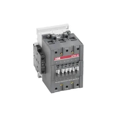
ABB Block Contactor 1SFL437001R6922 is a motor-starting and protection device designed for heavy-duty industrial applications. Its wide control voltage range helps standardize installations across varying supply standards, reducing wiring variants and downtime. This model carries CE conformity, UL/CSA listings, and RoHS compliance, with additional approvals such as ABS and RINA to support global deployment. With compact dimensions and accessible mounting, it offers a robust, install-friendly solution for conveyors, pumps, and machine tools while meeting IEC 60947-4-1 and related safety requirements.
Product Information
Extended Description
1SFL437001R6922 ABB: A 3-phase Contactor suitable for various applications such as Motor starting, Isolation, By-pass and Distribution application up to max 1000 V. Operated with wide control voltage range 48-130 V, AC/DC
Minimum Order Quantity
1 piece
Customs Tariff Number
85364900
Replacement Product ID (NEW)
1SBL407001R1222
Data Sheet, Technical Information
1SBC100192C0206
Instructions and Manuals
Contactors A95, A110, UA95, UA110, AF95, AF110, AE95, AE110, TAE95, TAE110
Dimension Diagram
53540923-1
Product Net Width
90 mm
Product Net Depth / Length
156.5 mm
Product Net Height
148 mm
Product Net Weight
1.9 kg
Number of Main Contacts NO
3
Number of Main Contacts NC
0
Number of Auxiliary Contacts NO
2
Number of Auxiliary Contacts NC
2
Number of Poles
3P
Rated Operational Voltage
Main Circuit 1000 V
Rated Frequency (f)
Main Circuit 50 / 60 Hz
Conventional Free-air Thermal Current (Ith)
acc. to IEC 60947-4-1, Open Contactors Θ = 40 °C 145 A
Rated Operational Current AC-1 (Ie)
(690 V) 40 °C 145 A | (690 V) 55 °C 135 A | (690 V) 70 °C 115 A
Rated Operational Current AC-3 (Ie)
(415 V) 55 °C 96 A | (440 V) 55 °C 93 A | (500 V) 55 °C 80 A | (690 V) 55 °C 65 A | (1000 V) 55 °C 30 A | (380 / 400 V) 55 °C 96 A | (220 / 230 / 240 V) 55 °C 96
Rated Operational Current DC-1 (Ie)
(110 V) 2 Poles in Series, 40 °C 145 A | (220 V) 3 Poles in Series, 40 °C 145 A
Rated Operational Current DC-3 (Ie)
(110 V) 2 Poles in Series, 40 °C 145 A | (220 V) 3 Poles in Series, 40 °C 145 A
Rated Operational Current DC-5 (Ie)
(110 V) 2 Poles in Series, 40 °C 145 A | (220 V) 3 Poles in Series, 40 °C 145 A
Rated Operational Power AC-3 (Pe)
(415 V) 55 kW | (440 V) 55 kW | (500 V) 55 kW | (690 V) 55 kW | (1000 V) 40 kW | (380 / 400 V) 45 kW | (220 / 230 / 240 V) 25 kW
Rated Breaking Capacity AC-3
8 x Ie AC-3
Rated Making Capacity AC-3
10 x Ie AC-3
Short-Circuit Protective Devices
gG Type Fuses 160 A
Maximum Breaking Capacity
cos phi=0.45 (cos phi=0.35 for Ie > 100 A) at 440 V 1160 A | cos phi=0.45 (cos phi=0.35 for Ie > 100 A) at 690 V 800 A
Rated Insulation Voltage (Ui)
acc. to IEC 60947-4-1 and VDE 0110 (Gr. C) 1000 V | acc. to UL/CSA 600 V
Rated Impulse Withstand Voltage (Uimp)
Main Circuit 8 kV
Maximum Electrical Switching Frequency
(AC-1) 300 cycles per hour | (AC-2 / AC-4) 150 cycles per hour | (AC-3) 300 cycles per hour
Mechanical Durability
10 million
Maximum Mechanical Switching Frequency
300 cycles per hour
Coil Operating Limits
(acc. to IEC 60947-4-1) 0.85 x Uc Min. ... 1.1 x Uc Max. (at θ ≤ 70 °C)
Rated Control Circuit Voltage (Uc)
50 Hz 48 ... 130 V | 60 Hz 48 ... 130 V | DC Operation 48 ... 130 V
Coil Consumption
Holding at Max. Rated Control Circuit Voltage 50 Hz 7 V·A | Holding at Max. Rated Control Circuit Voltage 60 Hz 7 V·A | Holding at Max. Rated Control Circuit Voltage DC 2 W | Pull-in at Max. Rated Control Circuit Voltage 50 Hz 350 V·A | Pull-in at Max. Rated Control Circuit Voltage 60 Hz 350 V·A | Pull-in at Max. Rated Control Circuit Voltage DC 400 W
Power Loss
at Rated Operating Conditions per Pole 3.5 W
Operate Time
Between Coil De-energization and NC Contact Closing 60 ... 130 ms | Between Coil De-energization and NO Contact Opening 55 ... 125 ms | Between Coil Energization and NC Contact Opening 27 ... 77 ms | Between Coil Energization and NO Contact Closing 30 ... 80 ms
Connecting Capacity Main Circuit
Bar 30 mm² | Flexible with Cable End 2 x 6 ... 35 mm² | Rigid 1 x 10 ... 95 mm²
Connecting Capacity Auxiliary Circuit
Flexible with Ferrule 2x 0.75 ... 2.5 mm² | Flexible with Insulated Ferrule 1x 0.75 ... 2.5 mm² | Flexible 2x0.75 ... 2.5 mm² | Solid 2 x 1 ... 4 mm² | Stranded 2 x 1 .... 4 mm²
Connecting Capacity
Bar 30 mm² | Flexible with Cable End 2 x 6 ... 35 mm² | Rigid 1 x 10 ... 95 mm²
Degree of Protection
acc. to IEC 60529, IEC 60947-1, EN 60529 Coil Terminals IP20 | acc. to IEC 60529, IEC 60947-1, EN 60529 Main Terminals IP10
Connecting Terminals (delivered in open position) Main Poles
M8 hexagon socket screw with single connector
Tightening Torque
Main Circuit 8 N·m
Terminal Type
Cable Clamp
Product Name
Block Contactor
Maximum Operating Voltage UL/CSA
Main Circuit 600 V
General Use Rating UL/CSA
(600 V AC) 125 A
Horsepower Rating UL/CSA
(200 V AC) Three Phase 30 hp | (208 V AC) Three Phase 30 hp | (220 ... 240 V AC) Three Phase 30 hp | (440 ... 480 V AC) Three Phase 60 hp | (550 ... 600 V AC) Three Phase 75 hp
Full Load Amps Motor Use
(440 ... 480 V AC) Three Phase 77 A | (550 ... 600 V AC) Three Phase 77 A
Ambient Air Temperature
Close to Contactor Fitted with Thermal O/L Relay (0.85 ... 1.1 Uc) -25 ... 50 °C | Close to Contactor without Thermal O/L Relay (0.85 ... 1.1 Uc) -40 ... 70 °C | Close to Contactor for Storage -60 ... +80 °C
Maximum Operating Altitude Permissible
Without Derating 3000 m
Resistance to Shock acc. to IEC 60068-2-27
Half-sine Pulse for 11 ms, No Change in Contact Position, Open, Shock Direction: A 20 g | Half-sine Pulse for 11 ms, No Change in Contact Position, Closed, Shock Direction: A 20 g | Half-sine Pulse for 11 ms, No Change in Contact Position, Closed, Shock Direction: B1 15 g | Half-sine Pulse for 11 ms, No Change in Contact Position, Closed, Shock Direction: C1 20 g | Half-sine Pulse for 11 ms, No Change in Contact Position, Closed, Shock Direction: C2 20 g | Half-sine Pulse for 11 ms, No Change in Contact Position, Open, Shock Direction: B1 5 g | Half-sine Pulse for 11 ms, No Change in Contact Position, Open, Shock Direction: B2 15 g | Half-sine Pulse for 11 ms, No Change in Contact Position, Open, Shock Direction: C1 20 g | Half-sine Pulse for 11 ms, No Change in Contact Position, Open, Shock Direction: C2 20 g
RoHS Information
CE Declaration of Conformity - Contactor - A(F)95...A(F)300, AM110...AM300, UA95...UA110, (T)AE95....(T)AE110
RoHS Status
Following EU Directive 2011/65/EU
WEEE B2C / B2B
Business To Business
WEEE Category
5. Small Equipment (No External Dimension More Than 50 cm)
ABS Certificate
ABS Certificate, Contactor, AF400...AF2050 (Sweden)
BV Certificate
BV Certificate, Contactor, AF400 ... AF2850
CB Certificate
SE-73661
CCS Certificate
CCS Certificate, Contactor, AF116 to AF2850 (Sweden)
CQC Certificate
CQC Certificate, Contactor, AF95, AF95...RT, AF95B...RT, AF110, AF110...RT, AF110B...RT, Made in Sweden | CQC Certificate, Contactor, AF95-30, AF95-30-11, AF110-30, AF110-30-11, Made in China
Declaration of Conformity - CCC
CCC Declaration of Conformity, Contactor, AF95, AF95...RT, AF95B...RT, AF110, AF110...RT, AF110B...RT, Made in Sweden | CCC Declaration of Conformity, Contactor, AF95-30, AF95-30-11, AF110-30, AF110-30-11, Made in China
Declaration of Conformity - CE
CE Declaration of Conformity - Contactor - A(F)95...A(F)300, AM110...AM300, UA95...UA110, (T)AE95....(T)AE110
DNV GL Certificate
DNV Certificate, Contactor, AF400...AF2850
EAC Certificate
9AKK107046A8618
GL Certificate
GL_20260-04HH
LR Certificate
Lloyds register Certificate, Contactor, AF400...AF2850
RINA Certificate
RINA Certificate, AF95, AF110, AF145, AF185, AF210, AF260, AF300, AF400, AF460, AF580, AF750, AF1250, AF1350, AF1650, AF2050, AF2650, AF116, AF140, AF146, AF190, AF205, AF265, AF305, AF370
RMRS Certificate
RMRS_12-03683-315
Package Level 1 Units
box 1 piece
Package Level 1 Width
170 mm
Package Level 1 Depth / Length
140 mm
Package Level 1 Height
170 mm
Package Level 1 Gross Weight
2.1 kg
Package Level 1 EAN
7320500237380
Object Classification Code
Q
ETIM 7
EC000066 - Power contactor, AC switching
ETIM 8
EC000066 - Power contactor, AC switching
ETIM 9
EC000066 - Power contactor, AC switching
eClass
V11.0 : 27371003
UNSPSC
39121529
IDEA Granular Category Code (IGCC)
4755 >> Contactors
Feature: Three main contacts and a 3P configuration enable reliable motor switching at high voltages. Business Impact: Supports efficient motor starting and safe isolation, reducing wear on contact sets and extending drive life in industrial lines. Application: Suitable for machine tools, conveyors, and pumps where precise motor control is essential. Feature: Wide control circuit voltage 48–130 V AC/DC across 50/60 Hz. Business Impact: Simplifies stock and wiring by accommodating varying plant voltages, cutting installation time. Application: Flexible for mixed-voltage environments and retrofit projects. Feature: Rated insulation voltage up to 1000 V and impulse withstand 8 kV. Business Impact: Enhances safety margins and regulatory compliance in high-risk electrical environments. Application: High-voltage motor control and distribution panels. Feature: 10 million mechanical operations and 300 cycles per hour switching. Business Impact: Delivers durable lifecycle performance with predictable maintenance scheduling. Application: Heavy-duty, high-cycle applications in manufacturing lines. Feature: Coil consumption and power dynamics (holding 2 W; pull-in up to 400 W). Business Impact: Lower energy use during standby, faster pull-in, and reduced thermal stress. Application: Continuous-duty control circuits and energy-conscious installations. Feature: Connecting capacity for main and auxiliary circuits (bar 30 mm²; flex 2 x 6…35 mm²; rigid 1 x 10…95 mm²). Business Impact: Simplifies field wiring and enables robust, heat-resistant terminations. Application: Panel builders and service technicians wiring complex motor starters. Feature: IP20 coil terminals and IP10 main terminals. Business Impact: Safer assembly with easy accessibility and improved protection in clean-room or workshop environments. Application: Control cabinets and equipment bays with routine maintenance.
Get a Quick Quote for a ABB 1SFL437001R6922
Chat with us on WhatsApp - fast responses guaranteed
Need to speak with someone? We'll call you back within 2 hours during business hours
Interested in ABB 1SFL437001R6922?
Enquire Now
FAQs
When installing, ensure proper panel mounting within the 90 mm width and 156.5 mm depth footprint, secure main terminals with 8 N·m torque, and follow IP20 coil terminal protection guidelines. Verify compatible main circuit ratings up to 1000 V and use 30 mm² bar or 2 x 6–35 mm² flexible conductors for main connections. Plan for 3P operation and connect two auxiliary NO contacts for control signaling.
The device offers a 48–130 V control circuit across 50/60 Hz or DC operation, with coil power consumption of 2 W holding and up to 350–400 W pull-in depending on voltage. Main circuit ratings include up to 1000 V insulation voltage, 50/60 Hz operation, and AC-3 duty with rated currents up to 96 A at various voltages. It supports 3 main NO contacts and 2 auxiliary NO/NC contacts.
Yes. It is designed for motor starting, isolation, bypass, and distribution up to 1000 V main circuit, with AC-3 duty ratings and a rated short-circuit capacity. The device supports 3P operation and has a robust mechanical durability specification of 10 million cycles, making it appropriate for demanding motor control tasks in manufacturing.
The product carries CE conformity and UL/CSA listings, with RoHS compliance. Additional approvals include ABS, BV, GL, DNV GL, and RINA, providing broad international acceptance. These certifications support compliance in EU, North America, and marine/industrial sectors, aiding regulatory alignment for global procurement and cross-border projects.
Expect high durability with up to 10 million mechanical operations and a maximum switching frequency of 300 cycles per hour. The IP20 coil terminals and IP10 main terminals offer reliable protection, while the modular connections simplify field maintenance. This translates to lower downtime, predictable maintenance windows, and lower total cost of ownership in industrial plants.