ABB 1SFL437062R6911 Block Contactor - CE/UL 1000V
Part Number: 1SFL437062R6911
Quick Summary
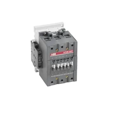
ABB 1SFL437062R6911 Block Contactor is a high-capacity switching device for railway and industrial power control. It accommodates a wide coil range of 48-130 V AC, DC operation, enabling reliable operation across fluctuating supply conditions. Engineers often struggle with compatibility and regulatory compliance in mixed-voltage environments; this model addresses those challenges with IEC/EN 60947-4-1 and UL 60947-4-1 family standards, plus CE and UL recognition. The product’s IP20 coil terminals and IP10 main terminals provide safe enclosure integration, while its robust 3P construction supports demanding loads. By combining versatility with verified performance, this contactor supports spare-part commonality, reduces inventory, and accelerates electrical panel assemblies in rail and general automation projects.
Product Information
Extended Description
1SFL437062R6911 ABB: A 3-phase Contactor suitable for Rail way applications application. Operated with a wide voltage control voltage range 48-130 V, AC/DC
Minimum Order Quantity
1 piece
Customs Tariff Number
85364900
Data Sheet, Technical Information
1SBC100192C0206
Instructions and Manuals
Contactors A95, A110, UA95, UA110, AF95, AF110, AE95, AE110, TAE95, TAE110
Dimension Diagram
1SFB535001G1005
Product Net Width
102 mm
Product Net Depth / Length
123.5 mm
Product Net Height
148 mm
Product Net Weight
1.9 kg
Number of Main Contacts NO
3
Number of Main Contacts NC
0
Number of Auxiliary Contacts NO
1
Number of Auxiliary Contacts NC
1
Number of Poles
3P
Standards
IEC/EN 60947-1, IEC/EN 60947-4-1, UL 60947-4-1, CSA C22.2 No. 60947-4-1, IEC 60077-1 (applicable parts), IEC 60077-2 (applicable parts), EN 50155 (applicable parts), TR CU 001/2011, IEC 61373, For compliance confirmation on applicable parts based on your application and combination, please consult your ABB sales representatives.
Rated Operational Voltage
Main Circuit 1000 V
Rated Frequency (f)
Main Circuit 50 / 60 Hz
Conventional Free-air Thermal Current (Ith)
acc. to IEC 60947-4-1, Open Contactors Θ = 40 °C 145 A
Rated Operational Current AC-1 (Ie)
(690 V) 40 °C 145 A | (690 V) 55 °C 135 A | (690 V) 70 °C 115 A
Rated Operational Current AC-3 (Ie)
(415 V) 55 °C 96 A | (440 V) 55 °C 93 A | (500 V) 55 °C 80 A | (690 V) 55 °C 65 A | (1000 V) 55 °C 30 A | (380 / 400 V) 55 °C 96 A | (220 / 230 / 240 V) 55 °C 96
Rated Operational Current DC-1 (Ie)
(110 V) 2 Poles in Series, 40 °C 145 A | (110 V) 2 Poles in Series, 55 °C 135 A | (110 V) 2 Poles in Series, 70 °C 115 A | (110 V) 3 Poles in Series, 40 °C 145 A | (110 V) 3 Poles in Series, 55 °C 135 A | (110 V) 3 Poles in Series, 70 °C 115 A | (220 V) 3 Poles in Series, 40 °C 145 A | (220 V) 3 Poles in Series, 55 °C 135 A | (220 V) 3 Poles in Series, 70 °C 115 A
Rated Operational Current DC-3 (Ie)
(110 V) 2 Poles in Series, 40 °C 145 A | (110 V) 2 Poles in Series, 55 °C 135 A | (110 V) 2 Poles in Series, 70 °C 115 A | (110 V) 3 Poles in Series, 40 °C 145 A | (110 V) 3 Poles in Series, 55 °C 135 A | (110 V) 3 Poles in Series, 70 °C 115 A | (220 V) 3 Poles in Series, 40 °C 145 A | (220 V) 3 Poles in Series, 55 °C 135 A | (220 V) 3 Poles in Series, 70 °C 115 A | (72 V) 1-Pole, 40 °C 130 A | (72 V) 1-Pole, 55 °C 130 A | (72 V) 1-Pole, 70 °C 115 A
Rated Operational Current DC-5 (Ie)
(110 V) 2 Poles in Series, 40 °C 145 A | (110 V) 2 Poles in Series, 55 °C 135 A | (110 V) 2 Poles in Series, 70 °C 115 A | (110 V) 3 Poles in Series, 40 °C 145 A | (110 V) 3 Poles in Series, 55 °C 135 A | (110 V) 3 Poles in Series, 70 °C 115 A | (220 V) 3 Poles in Series, 40 °C 145 A | (220 V) 3 Poles in Series, 55 °C 135 A | (220 V) 3 Poles in Series, 70 °C 115 A
Rated Operational Power AC-3 (Pe)
(415 V) 55 kW | (440 V) 55 kW | (500 V) 55 kW | (690 V) 55 kW | (1000 V) 40 kW | (380 / 400 V) 45 kW | (220 / 230 / 240 V) 25 kW
Rated Breaking Capacity AC-3
8 x Ie AC-3
Rated Making Capacity AC-3
10 x Ie AC-3
Short-Circuit Protective Devices
gG Type Fuses 160 A
Maximum Breaking Capacity
cos phi=0.45 (cos phi=0.35 for Ie > 100 A) at 440 V 1160 A | cos phi=0.45 (cos phi=0.35 for Ie > 100 A) at 690 V 800 A
Rated Insulation Voltage (Ui)
acc. to IEC 60947-4-1 and VDE 0110 (Gr. C) 1000 V | acc. to UL/CSA 600 V
Rated Impulse Withstand Voltage (Uimp)
Main Circuit 8 kV
Maximum Electrical Switching Frequency
(AC-1) 300 cycles per hour | (AC-2 / AC-4) 150 cycles per hour | (AC-3) 300 cycles per hour
Mechanical Durability
10 million
Maximum Mechanical Switching Frequency
300 cycles per hour
Coil Operating Limits
(acc. to IEC 60947-4-1) 0.85 x Uc Min. ... 1.1 x Uc Max. (at θ ≤ 70 °C)
Rated Control Circuit Voltage (Uc)
50 Hz 48 ... 130 V | 60 Hz 48 ... 130 V | DC Operation 48 ... 130 V
Coil Consumption
Holding at Max. Rated Control Circuit Voltage 50 Hz 7 V·A | Holding at Max. Rated Control Circuit Voltage 60 Hz 7 V·A | Holding at Max. Rated Control Circuit Voltage DC 2 W | Pull-in at Max. Rated Control Circuit Voltage 50 Hz 350 V·A | Pull-in at Max. Rated Control Circuit Voltage 60 Hz 350 V·A | Pull-in at Max. Rated Control Circuit Voltage DC 400 W
Power Loss
at Rated Operating Conditions per Pole 3.5 W
Operate Time
Between Coil De-energization and NC Contact Closing 60 ... 130 ms | Between Coil De-energization and NO Contact Opening 55 ... 125 ms | Between Coil Energization and NC Contact Opening 27 ... 77 ms | Between Coil Energization and NO Contact Closing 30 ... 80 ms
Connecting Capacity Main Circuit
Bar 30 mm² | Flexible with Cable End 2 x 6 ... 35 mm² | Rigid 1 x 10 ... 95 mm²
Connecting Capacity Auxiliary Circuit
Flexible with Ferrule 2x 0.75 ... 2.5 mm² | Flexible with Insulated Ferrule 2x 0.75 ... 2.5 mm² | Flexible 2x0.75 ... 2.5 mm² | Solid 2 x 1 ... 4 mm² | Stranded 2 x 1 .... 4 mm²
Connecting Capacity
Bar 30 mm² | Flexible with Cable End 2 x 6 ... 35 mm² | Rigid 2 x 6 ... 65 mm²
Degree of Protection
acc. to IEC 60529, IEC 60947-1, EN 60529 Coil Terminals IP20 | acc. to IEC 60529, IEC 60947-1, EN 60529 Main Terminals IP10
Connecting Terminals (delivered in open position) Main Poles
M8 hexagon socket screw with single connector
Tightening Torque
Main Circuit 8 N·m
Terminal Type
Ring-Tongue Terminals
Product Name
Block Contactor
Maximum Operating Voltage UL/CSA
Main Circuit 600 V
General Use Rating UL/CSA
(600 V AC) 125 A
Horsepower Rating UL/CSA
(120 V AC) Single Phase 7-1/2 hp | (200 ... 208 V AC) Three Phase 30 hp | (200 V AC) Three Phase 30 hp | (208 V AC) Three Phase 30 hp | (220 ... 240 V AC) Three Phase 30 hp | (240 V AC) Single Phase 20 hp | (440 ... 480 V AC) Three Phase 60 hp | (550 ... 600 V AC) Three Phase 75 hp
Full Load Amps Motor Use
(120 V AC) Single Phase 80 A | (200 ... 208 V AC) Three Phase 92 A | (220 ... 240 V AC) Three Phase 80 A | (240 V AC) Single Phase 88 A | (440 ... 480 V AC) Three Phase 77 A | (550 ... 600 V AC) Three Phase 77 A
Ambient Air Temperature
Close to Contactor Fitted with Thermal O/L Relay (0.85 ... 1.1 Uc) -25 ... 50 °C | Close to Contactor without Thermal O/L Relay (0.85 ... 1.1 Uc) -40 ... 70 °C | Close to Contactor for Storage -60 ... +80 °C
Maximum Operating Altitude Permissible
Without Derating 3000 m
Resistance to Shock acc. to IEC 60068-2-27
Half-sine Pulse for 11 ms, No Change in Contact Position, Open, Shock Direction: A 20 g | Half-sine Pulse for 11 ms, No Change in Contact Position, Closed, Shock Direction: A 20 g | Half-sine Pulse for 11 ms, No Change in Contact Position, Closed, Shock Direction: B1 15 g | Half-sine Pulse for 11 ms, No Change in Contact Position, Closed, Shock Direction: C1 20 g | Half-sine Pulse for 11 ms, No Change in Contact Position, Closed, Shock Direction: C2 20 g | Half-sine Pulse for 11 ms, No Change in Contact Position, Open, Shock Direction: B1 5 g | Half-sine Pulse for 11 ms, No Change in Contact Position, Open, Shock Direction: B2 15 g | Half-sine Pulse for 11 ms, No Change in Contact Position, Open, Shock Direction: C1 20 g | Half-sine Pulse for 11 ms, No Change in Contact Position, Open, Shock Direction: C2 20 g
Conflict Minerals Reporting Template (CMRT)
CMRT - Conflict Minerals Reporting Template
REACH Declaration
REACH - Letter of Confirmation for block contactors, contactor relays, installation contactors, mini contactors, mini contactor relays, thermal overload relays, electronic overload relays and related accessories
RoHS Information
RoHS II declaration for block contactors, installation contactors, mini contactors, mini contactor relays, thermal overload relays, electronic overload relays and related accessories
RoHS Status
Following EU Directive 2011/65/EU
Toxic Substances Control Act - TSCA
Toxic Substances Control Act (TSCA) declaration for Contactors
WEEE B2C / B2B
Business To Business
WEEE Category
5. Small Equipment (No External Dimension More Than 50 cm)
ABS Certificate
ABS Certificate, Contactor, AF400...AF2050 (Sweden)
BV Certificate
13409/C0 BV
CB Certificate
SE-73661
CQC Certificate
CQC Certificate, Contactor, AF95, AF95...RT, AF95B...RT, AF110, AF110...RT, AF110B...RT, Made in Sweden
Declaration of Conformity - CCC
CCC Declaration of Conformity, Contactor, AF95, AF95...RT, AF95B...RT, AF110, AF110...RT, AF110B...RT, Made in Sweden
Declaration of Conformity - CE
CE Declaration of Conformity - Contactor - A(F)95...A(F)300, AM110...AM300, UA95...UA110, (T)AE95....(T)AE110
Declaration of Conformity - UKCA
UK Declaration of Conformity - Contactors >100A
EAC Certificate
9AKK107046A8618
GL Certificate
GL_20260-04HH
LR Certificate
LR_04-00015-E1
RINA Certificate
ELE060313XG/002
RMRS Certificate
RMRS_12-03683-315
Package Level 1 Units
box 1 piece
Package Level 1 Width
130 mm
Package Level 1 Depth / Length
265 mm
Package Level 1 Height
162 mm
Package Level 1 Gross Weight
2.1 kg
Package Level 1 EAN
7320500260111
Object Classification Code
Q
ETIM 7
EC000066 - Power contactor, AC switching
ETIM 8
EC000066 - Power contactor, AC switching
ETIM 9
EC000066 - Power contactor, AC switching
eClass
V11.0 : 27371003
UNSPSC
39121529
IDEA Granular Category Code (IGCC)
4763 >> Power contactor, DC switching
Feature: Wide 48-130 V coil drive supports AC and DC operation, enabling a single device to cover multiple control schemes. Impact: Reduces inventory and simplifies panel design, delivering faster commissioning in mixed-voltage environments. Application: Railway traction and industrial automation where supply variability is common. Feature: Three main NO contacts plus one NO and one NC auxiliary contact on a 3P frame. Impact: Facilitates motor control with built-in signaling and status feedback, improving interlock logic and safety. Application: Starter circuits and control logics in conveyors or winch systems. Feature: Rated insulation voltage up to 1000 V and impulse withstand of 8 kV. Impact: Enhances insulation margins and reliability in high-energy switching environments, reducing failure risk. Application: High-voltage line switching and traction-related panels. Feature: Mechanical durability rated at 10 million operations and maximum mechanical switching frequency of 300 cycles per hour. Impact: Longer service life reduces maintenance cycles and total cost of ownership. Application: Frequent on/off control in automated plants and rail applications. Feature: Robust connection capacities for main and auxiliary circuits (busbars, flexible, rigid, and ferrule options) with IP20/IP10 protection. Impact: Easier field installation, safer terminations, and compatible with standard enclosures. Application: Panel assemblies requiring reliable, field-terminable connections. Feature: Comprehensive certifications and regulatory compliance (CE, UL/CSA, UKCA, CCC, EAC, GL, LR, RINA). Impact: Streamlines cross-border deployment and customer acceptance, reducing compliance risk. Application: Global projects across rail, industrial, and energy sectors.
Get a Quick Quote for a ABB 1SFL437062R6911
Chat with us on WhatsApp - fast responses guaranteed
Need to speak with someone? We'll call you back within 2 hours during business hours
Interested in ABB 1SFL437062R6911?
Enquire Now
FAQs
The contactor is delivered with main poles in an open position, using M8 hexagon socket screws for mounting. Main terminals accept ring-tongue connections, and the product supports flexible and rigid wiring up to 95 mm² for the main circuit and 2x0.75–2.5 mm² for auxiliary circuits. It measures 102 mm wide, 123.5 mm deep, and 148 mm tall, with a net weight of 1.9 kg, simplifying enclosure fit and service.
AC-3 ratings vary by voltage and ambient temperature, for example up to 96 A at 415–500 V and up to 96 A at 380/400 V with 55°C conditions, while DC-3 ratings cover configurations like 110 V with multiple poles in series. These ratings enable reliable motor switching and starting in diversified power networks, with explicit values provided per application in the datasheet.
Yes. It features a wide 48–130 V control voltage range (AC/DC), high insulation (1000 V), and 8 kV impulse withstand, plus CE/UL/UKCA certification and robust mechanical durability. Its three main contacts and integrated auxiliary contacts support signaling and interlock schemes, while IP20/IP10 protection simplifies enclosure integration in rail and automation environments.
This model carries CE, UL/CSA recognition, UKCA labeling, CCC, and multiple third-party certificates such as EAC, GL, LR, RINA, and CB. It also aligns with REACH and RoHS declarations. These certifications reduce regulatory risk and support global deployment in industrial and rail applications.
With a rated mechanical durability of 10 million cycles and a maximum switching frequency of 300 cycles per hour, maintenance intervals are extended, reducing downtime. Coil consumption values (holding 50 Hz at 7 VA; pull-in up to 350–400 VA) support energy efficiency. The wide coil range and common IEC/EN standards also minimize spare parts diversity, driving lower lifecycle costs.