ABB 1SFL437062R7011 Block Contactor - CE & UL/CSA
Part Number: 1SFL437062R7011
Quick Summary
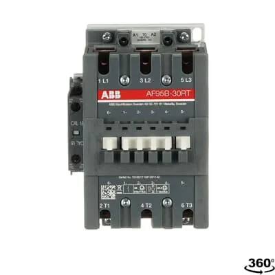
ABB 1SFL437062R7011 Block Contactor is a 3‑phase switch designed for railway and industrial drive applications. This device operates across a wide control voltage range of 100–250 V AC/DC, enabling flexible remote control without coil changes. It complies with IEC/EN 60947-1 and 60947-4-1, and carries CE and UKCA declarations for global compliance. In compact control panels it provides three main NO contacts plus one NO and one NC auxiliary contact, consolidating control and protection. Designed for rail and industrial uses, it integrates easily with standard wiring practices, offers IP20 coil terminals and IP10 main terminals, and supports robust, maintenance-friendly installations, delivering reliability and lifecycle cost advantages.
Product Information
Extended Description
1SFL437062R7011 ABB: A 3-phase Contactor suitable for Rail way applications application. Operated with a wide voltage control voltage range 100-250 V, AC/DC
Minimum Order Quantity
1 piece
Customs Tariff Number
85364900
Data Sheet, Technical Information
1SBC100192C0206
Instructions and Manuals
Contactors A95, A110, UA95, UA110, AF95, AF110, AE95, AE110, TAE95, TAE110
Dimension Diagram
1SFB535001G1005
Product Net Width
102 mm
Product Net Depth / Length
123.5 mm
Product Net Height
148 mm
Product Net Weight
1.9 kg
Number of Main Contacts NO
3
Number of Main Contacts NC
0
Number of Auxiliary Contacts NO
1
Number of Auxiliary Contacts NC
1
Number of Poles
3P
Standards
IEC/EN 60947-1, IEC/EN 60947-4-1, UL 60947-4-1, CSA C22.2 No. 60947-4-1, IEC 60077-1 (applicable parts), IEC 60077-2 (applicable parts), EN 50155 (applicable parts), TR CU 001/2011, IEC 61373, For compliance confirmation on applicable parts based on your application and combination, please consult your ABB sales representatives.
Rated Operational Voltage
Main Circuit 1000 V
Rated Frequency (f)
Main Circuit 50 / 60 Hz
Conventional Free-air Thermal Current (Ith)
acc. to IEC 60947-4-1, Open Contactors Θ = 40 °C 145 A
Rated Operational Current AC-1 (Ie)
(690 V) 40 °C 145 A | (690 V) 55 °C 135 A | (690 V) 70 °C 115 A
Rated Operational Current AC-3 (Ie)
(415 V) 55 °C 96 A | (440 V) 55 °C 93 A | (500 V) 55 °C 80 A | (690 V) 55 °C 65 A | (1000 V) 55 °C 30 A | (380 / 400 V) 55 °C 96 A | (220 / 230 / 240 V) 55 °C 96
Rated Operational Current DC-1 (Ie)
(110 V) 2 Poles in Series, 40 °C 145 A | (110 V) 2 Poles in Series, 55 °C 135 A | (110 V) 2 Poles in Series, 70 °C 115 A | (110 V) 3 Poles in Series, 40 °C 145 A | (110 V) 3 Poles in Series, 55 °C 135 A | (110 V) 3 Poles in Series, 70 °C 115 A | (220 V) 3 Poles in Series, 40 °C 145 A | (220 V) 3 Poles in Series, 55 °C 135 A | (220 V) 3 Poles in Series, 70 °C 115 A
Rated Operational Current DC-3 (Ie)
(110 V) 2 Poles in Series, 40 °C 145 A | (110 V) 2 Poles in Series, 55 °C 135 A | (110 V) 2 Poles in Series, 70 °C 115 A | (110 V) 3 Poles in Series, 40 °C 145 A | (110 V) 3 Poles in Series, 55 °C 135 A | (110 V) 3 Poles in Series, 70 °C 115 A | (220 V) 3 Poles in Series, 40 °C 145 A | (220 V) 3 Poles in Series, 55 °C 135 A | (220 V) 3 Poles in Series, 70 °C 115 A | (72 V) 1-Pole, 40 °C 130 A | (72 V) 1-Pole, 55 °C 130 A | (72 V) 1-Pole, 70 °C 115 A
Rated Operational Current DC-5 (Ie)
(110 V) 2 Poles in Series, 40 °C 145 A | (110 V) 2 Poles in Series, 55 °C 135 A | (110 V) 2 Poles in Series, 70 °C 115 A | (110 V) 3 Poles in Series, 40 °C 145 A | (110 V) 3 Poles in Series, 55 °C 135 A | (110 V) 3 Poles in Series, 70 °C 115 A | (220 V) 3 Poles in Series, 40 °C 145 A | (220 V) 3 Poles in Series, 55 °C 135 A | (220 V) 3 Poles in Series, 70 °C 115 A
Rated Operational Power AC-3 (Pe)
(415 V) 55 kW | (440 V) 55 kW | (500 V) 55 kW | (690 V) 55 kW | (1000 V) 40 kW | (380 / 400 V) 45 kW | (220 / 230 / 240 V) 25 kW
Rated Breaking Capacity AC-3
8 x Ie AC-3
Rated Making Capacity AC-3
10 x Ie AC-3
Short-Circuit Protective Devices
gG Type Fuses 160 A
Maximum Breaking Capacity
cos phi=0.45 (cos phi=0.35 for Ie > 100 A) at 440 V 1160 A | cos phi=0.45 (cos phi=0.35 for Ie > 100 A) at 690 V 800 A
Rated Insulation Voltage (Ui)
acc. to IEC 60947-4-1 and VDE 0110 (Gr. C) 1000 V | acc. to UL/CSA 600 V
Rated Impulse Withstand Voltage (Uimp)
Main Circuit 8 kV
Maximum Electrical Switching Frequency
(AC-1) 300 cycles per hour | (AC-2 / AC-4) 150 cycles per hour | (AC-3) 300 cycles per hour
Mechanical Durability
10 million
Maximum Mechanical Switching Frequency
300 cycles per hour
Coil Operating Limits
(acc. to IEC 60947-4-1) 0.85 x Uc Min. ... 1.1 x Uc Max. (at θ ≤ 70 °C)
Rated Control Circuit Voltage (Uc)
50 Hz 100 ... 250 V | 60 Hz 100 ... 250 V | DC Operation 100 ... 250 V
Coil Consumption
Holding at Max. Rated Control Circuit Voltage 50 Hz 7 V·A | Holding at Max. Rated Control Circuit Voltage 60 Hz 7 V·A | Holding at Max. Rated Control Circuit Voltage DC 2 W | Pull-in at Max. Rated Control Circuit Voltage 50 Hz 350 V·A | Pull-in at Max. Rated Control Circuit Voltage 60 Hz 350 V·A | Pull-in at Max. Rated Control Circuit Voltage DC 400 W
Power Loss
at Rated Operating Conditions per Pole 3.5 W
Operate Time
Between Coil De-energization and NC Contact Closing 60 ... 130 ms | Between Coil De-energization and NO Contact Opening 55 ... 125 ms | Between Coil Energization and NC Contact Opening 27 ... 77 ms | Between Coil Energization and NO Contact Closing 30 ... 80 ms
Connecting Capacity Main Circuit
Bar 30 mm² | Flexible with Cable End 2 x 6 ... 35 mm² | Rigid 1 x 10 ... 95 mm²
Connecting Capacity Auxiliary Circuit
Flexible with Ferrule 2x 0.75 ... 2.5 mm² | Flexible with Insulated Ferrule 2x 0.75 ... 2.5 mm² | Flexible 2x0.75 ... 2.5 mm² | Solid 2 x 1 ... 4 mm² | Stranded 2 x 1 .... 4 mm²
Connecting Capacity
Bar 30 mm² | Flexible with Cable End 2 x 6 ... 35 mm² | Rigid 2 x 6 ... 65 mm²
Degree of Protection
acc. to IEC 60529, IEC 60947-1, EN 60529 Coil Terminals IP20 | acc. to IEC 60529, IEC 60947-1, EN 60529 Main Terminals IP10
Connecting Terminals (delivered in open position) Main Poles
M8 hexagon socket screw with single connector
Tightening Torque
Main Circuit 8 N·m
Terminal Type
Ring-Tongue Terminals
Product Name
Block Contactor
Maximum Operating Voltage UL/CSA
Main Circuit 600 V
General Use Rating UL/CSA
(600 V AC) 125 A
Horsepower Rating UL/CSA
(120 V AC) Single Phase 7-1/2 hp | (200 ... 208 V AC) Three Phase 30 hp | (200 V AC) Three Phase 30 hp | (208 V AC) Three Phase 30 hp | (220 ... 240 V AC) Three Phase 30 hp | (240 V AC) Single Phase 20 hp | (440 ... 480 V AC) Three Phase 60 hp | (550 ... 600 V AC) Three Phase 75 hp
Full Load Amps Motor Use
(120 V AC) Single Phase 80 A | (200 ... 208 V AC) Three Phase 92 A | (220 ... 240 V AC) Three Phase 80 A | (240 V AC) Single Phase 88 A | (440 ... 480 V AC) Three Phase 77 A | (550 ... 600 V AC) Three Phase 77 A
Ambient Air Temperature
Close to Contactor Fitted with Thermal O/L Relay (0.85 ... 1.1 Uc) -25 ... 50 °C | Close to Contactor without Thermal O/L Relay (0.85 ... 1.1 Uc) -40 ... 70 °C | Close to Contactor for Storage -60 ... +80 °C
Maximum Operating Altitude Permissible
Without Derating 3000 m
Resistance to Shock acc. to IEC 60068-2-27
Half-sine Pulse for 11 ms, No Change in Contact Position, Open, Shock Direction: A 20 g | Half-sine Pulse for 11 ms, No Change in Contact Position, Closed, Shock Direction: A 20 g | Half-sine Pulse for 11 ms, No Change in Contact Position, Closed, Shock Direction: B1 15 g | Half-sine Pulse for 11 ms, No Change in Contact Position, Closed, Shock Direction: C1 20 g | Half-sine Pulse for 11 ms, No Change in Contact Position, Closed, Shock Direction: C2 20 g | Half-sine Pulse for 11 ms, No Change in Contact Position, Open, Shock Direction: B1 5 g | Half-sine Pulse for 11 ms, No Change in Contact Position, Open, Shock Direction: B2 15 g | Half-sine Pulse for 11 ms, No Change in Contact Position, Open, Shock Direction: C1 20 g | Half-sine Pulse for 11 ms, No Change in Contact Position, Open, Shock Direction: C2 20 g
Conflict Minerals Reporting Template (CMRT)
CMRT - Conflict Minerals Reporting Template
REACH Declaration
REACH - Letter of Confirmation for block contactors, contactor relays, installation contactors, mini contactors, mini contactor relays, thermal overload relays, electronic overload relays and related accessories
RoHS Information
RoHS II declaration for block contactors, installation contactors, mini contactors, mini contactor relays, thermal overload relays, electronic overload relays and related accessories
RoHS Status
Following EU Directive 2011/65/EU
Toxic Substances Control Act - TSCA
Toxic Substances Control Act (TSCA) declaration for Contactors
WEEE B2C / B2B
Business To Business
WEEE Category
5. Small Equipment (No External Dimension More Than 50 cm)
ABS Certificate
ABS Certificate, Contactor, AF400...AF2050 (Sweden)
BV Certificate
13409/C0 BV
CB Certificate
SE-73661
CQC Certificate
CQC Certificate, Contactor, AF95, AF95...RT, AF95B...RT, AF110, AF110...RT, AF110B...RT, Made in Sweden
Declaration of Conformity - CCC
CCC Declaration of Conformity, Contactor, AF95, AF95...RT, AF95B...RT, AF110, AF110...RT, AF110B...RT, Made in Sweden
Declaration of Conformity - CE
CE Declaration of Conformity - Contactor - A(F)95...A(F)300, AM110...AM300, UA95...UA110, (T)AE95....(T)AE110
Declaration of Conformity - UKCA
UK Declaration of Conformity - Contactors >100A
EAC Certificate
9AKK107046A8618
GL Certificate
GL_20260-04HH
LR Certificate
LR_04-00015-E1
RINA Certificate
ELE060313XG/002
RMRS Certificate
RMRS_12-03683-315
Package Level 1 Units
box 1 piece
Package Level 1 Width
130 mm
Package Level 1 Depth / Length
265 mm
Package Level 1 Height
162 mm
Package Level 1 Gross Weight
2.1 kg
Package Level 1 EAN
7320500260128
Object Classification Code
Q
ETIM 7
EC000066 - Power contactor, AC switching
ETIM 8
EC000066 - Power contactor, AC switching
ETIM 9
EC000066 - Power contactor, AC switching
eClass
V11.0 : 27371003
UNSPSC
39121529
IDEA Granular Category Code (IGCC)
4763 >> Power contactor, DC switching
E-Number (Norway)
4115320
E-Number (Sweden)
4115320
Feature: Wide coil control voltage 100–250 V AC/DC → Business Impact: Flexible control across varied supply conditions reduces panel stocking and wiring complexity; Application: Suitable for mixed electrical environments in railway systems and industrial drives. Feature: Three main NO contacts plus one NO and one NC auxiliary contact → Business Impact: Simplified logic with fewer components lowers installation time and maintenance cost; Application: Motor control with integrated signaling. Feature: Rated operational current AC-3 up to 96 A at higher voltages → Business Impact: Efficiently drives medium-sized motors with proven performance in 415–690 V networks; Application: Traction systems and conveyor drives. Feature: Mechanical durability of 10 million cycles → Business Impact: Long lifecycle reduces downtime and replacement costs in demanding environments; Application: High-cycle rail and factory switching. Feature: Protection and connectivity specs including IP20 coil terminals and IP10 main terminals → Business Impact: Safer, reliable wiring and easier field installation; Application: Panel-building and retrofit projects. Feature: Compliance with IEC/EN 60947-1, 60947-4-1, UL/CSA and CE/UKCA declarations → Business Impact: Global regulatory alignment minimizes compliance risk for international deployments; Application: Global supply chains and multi-region installations.
Get a Quick Quote for a ABB 1SFL437062R7011
Chat with us on WhatsApp - fast responses guaranteed
Need to speak with someone? We'll call you back within 2 hours during business hours
Interested in ABB 1SFL437062R7011?
Enquire Now
FAQs
Install the unit with the main terminals wired to 30 mm² bus or 2 x 6–35 mm² flexible conductors, and the auxiliary circuit wiring via 0.75–4 mm² ferruleable conductors. Use the 8 N·m tightening torque for main circuit terminals and ensure IP20/IP10 protections are respected. Coil control voltage is 100–250 V, suitable for AC or DC operation.
AC-3 ratings vary by voltage: up to 96 A at 415–690 V (55 °C) and down to 65 A at 690–1000 V. DC-3 ratings cover multiple configurations, including 110 V with 2–3 poles in series, maintaining 115–145 A depending on temperature. This supports reliable motor starting and braking in rail and conveyor drives.
Yes. It is designed for railway and industrial drives with a wide control voltage (100–250 V) and up to 1000 V main circuit capability. It meets IEC/EN 60947-1, 60947-4-1, UL/CSA standards and carries CE/UKCA declarations, making it appropriate for rolling stock panels and rail subsystem installations.
The AF95/AF95B family, including 1SFL437062R7011, carries CE, UKCA declarations, UL/CSA listings, CCC, ABS, BV, GL, LR, RINA and other major certificates. This broad compliance simplifies multi-region deployments and reduces regulatory risk in global projects.
With a mechanical durability rating of 10 million cycles and a per-pole power loss of 3.5 W, the device minimizes wear and energy waste. Combined with robust IP-rated terminals and reliable switching (AC-3 up to 96 A), the solution lowers downtime, extends service intervals, and yields favorable total cost of ownership in demanding environments.