ABB 1SFL437063R7211 Block Contactor - CE Certification
Part Number: 1SFL437063R7211
Quick Summary
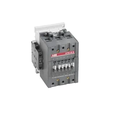
ABB 1SFL437063R7211 Block Contactor is a DC‑coil control device designed for railway and industrial drive applications, delivering reliable switching of three‑phase loads. This setup addresses the common challenge of managing multiple coil voltages by offering a wide 20–60 V DC control range in a single unit. With three main normally open contacts and one NO plus one NC auxiliary contact, it simplifies panel wiring while preserving safe, defined interlocks. The device carries CE, UL/CSA, and UKCA declarations, including IEC 60947‑4‑1 compatibility, and its insulation rating reaches 1000 V for reliable separation. In addition, robust mechanical durability and a compact footprint support long service life in demanding environments, delivering value through reduced downtime and simplified procurement.
Product Information
Extended Description
1SFL437063R7211 ABB: A 3-phase Contactor suitable for Rail way applications application. Operated with a wide voltage control voltage range 20-60V, DC
Minimum Order Quantity
1 piece
Customs Tariff Number
85364900
Data Sheet, Technical Information
1SBC100192C0206
Instructions and Manuals
Contactors A95, A110, UA95, UA110, AF95, AF110, AE95, AE110, TAE95, TAE110
Dimension Diagram
53540923-1
Product Net Width
102 mm
Product Net Depth / Length
123.5 mm
Product Net Height
148 mm
Product Net Weight
1.9 kg
Number of Main Contacts NO
3
Number of Main Contacts NC
0
Number of Auxiliary Contacts NO
1
Number of Auxiliary Contacts NC
1
Number of Poles
3P
Standards
IEC/EN 60947-1, IEC/EN 60947-4-1, UL 60947-4-1, CSA C22.2 No. 60947-4-1, IEC 60077-1 (applicable parts), IEC 60077-2 (applicable parts), EN 50155 (applicable parts), TR CU 001/2011, IEC 61373, For compliance confirmation on applicable parts based on your application and combination, please consult your ABB sales representatives.
Rated Operational Voltage
Main Circuit 1000 V
Conventional Free-air Thermal Current (Ith)
acc. to IEC 60947-4-1, Open Contactors Θ = 40 °C 145 A
Rated Operational Current AC-1 (Ie)
(690 V) 40 °C 145 A | (690 V) 55 °C 135 A | (690 V) 70 °C 115 A
Rated Operational Current AC-3 (Ie)
(415 V) 55 °C 96 A | (440 V) 55 °C 93 A | (500 V) 55 °C 80 A | (690 V) 55 °C 65 A | (1000 V) 55 °C 30 A | (380 / 400 V) 55 °C 96 A | (220 / 230 / 240 V) 55 °C 96
Rated Operational Current DC-1 (Ie)
(110 V) 2 Poles in Series, 40 °C 145 A | (110 V) 2 Poles in Series, 55 °C 135 A | (110 V) 2 Poles in Series, 70 °C 115 A | (110 V) 3 Poles in Series, 40 °C 145 A | (110 V) 3 Poles in Series, 55 °C 135 A | (110 V) 3 Poles in Series, 70 °C 115 A | (220 V) 3 Poles in Series, 40 °C 145 A | (220 V) 3 Poles in Series, 55 °C 135 A | (220 V) 3 Poles in Series, 70 °C 115 A
Rated Operational Current DC-3 (Ie)
(110 V) 2 Poles in Series, 40 °C 145 A | (110 V) 2 Poles in Series, 55 °C 135 A | (110 V) 2 Poles in Series, 70 °C 115 A | (110 V) 3 Poles in Series, 40 °C 145 A | (110 V) 3 Poles in Series, 55 °C 135 A | (110 V) 3 Poles in Series, 70 °C 115 A | (220 V) 3 Poles in Series, 40 °C 145 A | (220 V) 3 Poles in Series, 55 °C 135 A | (220 V) 3 Poles in Series, 70 °C 115 A | (72 V) 1-Pole, 40 °C 130 A | (72 V) 1-Pole, 55 °C 130 A | (72 V) 1-Pole, 70 °C 115 A
Rated Operational Current DC-5 (Ie)
(110 V) 2 Poles in Series, 40 °C 145 A | (110 V) 2 Poles in Series, 55 °C 135 A | (110 V) 2 Poles in Series, 70 °C 115 A | (110 V) 3 Poles in Series, 40 °C 145 A | (110 V) 3 Poles in Series, 55 °C 135 A | (110 V) 3 Poles in Series, 70 °C 115 A | (220 V) 3 Poles in Series, 40 °C 145 A | (220 V) 3 Poles in Series, 55 °C 135 A | (220 V) 3 Poles in Series, 70 °C 115 A
Rated Operational Power AC-3 (Pe)
(415 V) 55 kW | (440 V) 55 kW | (500 V) 55 kW | (690 V) 55 kW | (1000 V) 40 kW | (380 / 400 V) 45 kW | (220 / 230 / 240 V) 25 kW
Rated Breaking Capacity AC-3
8 x Ie AC-3
Rated Making Capacity AC-3
10 x Ie AC-3
Short-Circuit Protective Devices
gG Type Fuses 160 A
Maximum Breaking Capacity
cos phi=0.45 (cos phi=0.35 for Ie > 100 A) at 440 V 1160 A | cos phi=0.45 (cos phi=0.35 for Ie > 100 A) at 690 V 800 A
Rated Insulation Voltage (Ui)
acc. to IEC 60947-4-1 and VDE 0110 (Gr. C) 1000 V | acc. to UL/CSA 600 V
Rated Impulse Withstand Voltage (Uimp)
Main Circuit 8 kV
Maximum Electrical Switching Frequency
(AC-1) 300 cycles per hour | (AC-2 / AC-4) 150 cycles per hour | (AC-3) 300 cycles per hour
Mechanical Durability
10 million
Maximum Mechanical Switching Frequency
300 cycles per hour
Coil Operating Limits
(acc. to IEC 60947-4-1) 0.85 x Uc Min. ... 1.1 x Uc Max. (at θ ≤ 70 °C)
Rated Control Circuit Voltage (Uc)
DC Operation 20 ... 60 V
Coil Consumption
Holding at Max. Rated Control Circuit Voltage 50 Hz 7 V·A | Holding at Max. Rated Control Circuit Voltage 60 Hz 7 V·A | Holding at Max. Rated Control Circuit Voltage DC 2 W | Pull-in at Max. Rated Control Circuit Voltage 50 Hz 350 V·A | Pull-in at Max. Rated Control Circuit Voltage 60 Hz 350 V·A | Pull-in at Max. Rated Control Circuit Voltage DC 400 W
Power Loss
at Rated Operating Conditions per Pole 3.5 W
Operate Time
Between Coil De-energization and NC Contact Closing 60 ... 130 ms | Between Coil De-energization and NO Contact Opening 55 ... 125 ms | Between Coil Energization and NC Contact Opening 27 ... 77 ms | Between Coil Energization and NO Contact Closing 30 ... 80 ms
Connecting Capacity Main Circuit
Bar 30 mm² | Flexible with Cable End 2 x 6 ... 35 mm² | Rigid 2 x 6 ... 65 mm²
Connecting Capacity Auxiliary Circuit
Flexible with Ferrule 1x 0.75 ... 2.5 mm² | Flexible with Insulated Ferrule 1x 0.75 ... 2.5 mm² | Flexible 2x0.75 ... 2.5 mm² | Solid 2 x 1 ... 4 mm² | Stranded 2 x 1 .... 4 mm²
Connecting Capacity
Bar 30 mm² | Flexible with Cable End 2 x 6 ... 35 mm² | Rigid 2 x 6 ... 65 mm²
Degree of Protection
acc. to IEC 60529, IEC 60947-1, EN 60529 Coil Terminals IP20 | acc. to IEC 60529, IEC 60947-1, EN 60529 Main Terminals IP10
Connecting Terminals (delivered in open position) Main Poles
M8 hexagon socket screw with single connector
Tightening Torque
Main Circuit 8 N·m
Terminal Type
Cable Clamp
Product Name
Block Contactor
Maximum Operating Voltage UL/CSA
Main Circuit 600 V
General Use Rating UL/CSA
(600 V AC) 125 A
Horsepower Rating UL/CSA
(120 V AC) Single Phase 7-1/2 hp | (200 ... 208 V AC) Three Phase 30 hp | (200 V AC) Three Phase 30 hp | (208 V AC) Three Phase 30 hp | (220 ... 240 V AC) Three Phase 30 hp | (240 V AC) Single Phase 20 hp | (440 ... 480 V AC) Three Phase 60 hp | (550 ... 600 V AC) Three Phase 75 hp
Full Load Amps Motor Use
(120 V AC) Single Phase 80 A | (200 ... 208 V AC) Three Phase 92 A | (220 ... 240 V AC) Three Phase 80 A | (240 V AC) Single Phase 88 A | (440 ... 480 V AC) Three Phase 77 A | (550 ... 600 V AC) Three Phase 77 A
Ambient Air Temperature
Close to Contactor Fitted with Thermal O/L Relay (0.85 ... 1.1 Uc) -25 ... 50 °C | Close to Contactor without Thermal O/L Relay (0.85 ... 1.1 Uc) -40 ... 70 °C | Close to Contactor for Storage -60 ... +80 °C
Maximum Operating Altitude Permissible
Without Derating 3000 m
Resistance to Shock acc. to IEC 60068-2-27
Half-sine Pulse for 11 ms, No Change in Contact Position, Open, Shock Direction: A 20 g | Half-sine Pulse for 11 ms, No Change in Contact Position, Closed, Shock Direction: A 20 g | Half-sine Pulse for 11 ms, No Change in Contact Position, Closed, Shock Direction: B1 15 g | Half-sine Pulse for 11 ms, No Change in Contact Position, Closed, Shock Direction: C1 20 g | Half-sine Pulse for 11 ms, No Change in Contact Position, Closed, Shock Direction: C2 20 g | Half-sine Pulse for 11 ms, No Change in Contact Position, Open, Shock Direction: B1 5 g | Half-sine Pulse for 11 ms, No Change in Contact Position, Open, Shock Direction: B2 15 g | Half-sine Pulse for 11 ms, No Change in Contact Position, Open, Shock Direction: C1 20 g | Half-sine Pulse for 11 ms, No Change in Contact Position, Open, Shock Direction: C2 20 g
Conflict Minerals Reporting Template (CMRT)
CMRT - Conflict Minerals Reporting Template
REACH Declaration
REACH - Letter of Confirmation for block contactors, contactor relays, installation contactors, mini contactors, mini contactor relays, thermal overload relays, electronic overload relays and related accessories
RoHS Information
RoHS II declaration for block contactors, installation contactors, mini contactors, mini contactor relays, thermal overload relays, electronic overload relays and related accessories
RoHS Status
Following EU Directive 2011/65/EU
Toxic Substances Control Act - TSCA
Toxic Substances Control Act (TSCA) declaration for Contactors
WEEE B2C / B2B
Business To Business
WEEE Category
5. Small Equipment (No External Dimension More Than 50 cm)
BV Certificate
13409/C0 BV
CB Certificate
SE-73661
CQC Certificate
CQC Certificate, Contactor, AF95, AF95...RT, AF95B...RT, AF110, AF110...RT, AF110B...RT, Made in Sweden
Declaration of Conformity - CCC
CCC Declaration of Conformity, Contactor, AF95, AF95...RT, AF95B...RT, AF110, AF110...RT, AF110B...RT, Made in Sweden
Declaration of Conformity - CE
CE Declaration of Conformity - Contactor - A(F)95...A(F)300, AM110...AM300, UA95...UA110, (T)AE95....(T)AE110
Declaration of Conformity - UKCA
UK Declaration of Conformity - Contactors >100A
EAC Certificate
9AKK107046A8618
GL Certificate
GL_20260-04HH
LR Certificate
LR_04-00015-E1
RINA Certificate
ELE060313XG/002
RMRS Certificate
RMRS_12-03683-315
TÜV Certificate
MHM-EST-7.70017788e
Package Level 1 Units
box 1 piece
Package Level 1 Width
130 mm
Package Level 1 Depth / Length
265 mm
Package Level 1 Height
162 mm
Package Level 1 Gross Weight
2.1 kg
Package Level 1 EAN
7320500318072
Object Classification Code
Q
ETIM 7
EC000066 - Power contactor, AC switching
ETIM 8
EC000066 - Power contactor, AC switching
ETIM 9
EC000066 - Power contactor, AC switching
eClass
V11.0 : 27371003
UNSPSC
39121529
IDEA Granular Category Code (IGCC)
4755 >> Contactors
Feature → Business Impact → Application: The 3P block design with 3 normally open main contacts and 1 NO/1 NC auxiliary contact enables straightforward 3‑phase control in railway traction panels and industrial drives, reducing wiring complexity and panel size while improving reliability. The DC coil range of 20–60 V provides flexible control options and inventory simplification, enabling consistent operation across varying supply environments. Feature → Application: With a rated insulation voltage up to 1000 V and a UL/CSA rating, this device offers safe operation in mixed electrical zones and integration with protective relays, supporting compliant installations in rail and heavy industry. Feature → Objection Handling: Coil consumption values—holding 2 W on DC and pull‑in up to 400 W—allow accurate sizing for energy budgets and reduced thermal stress, addressing concerns about constant coil heat in confined panels. Feature → Compatibility: Connecting capacity for the main circuit (bar 30 mm², flexible 2×6–35 mm², rigid 2×6–65 mm²) and auxiliary circuits (ferrule or solid wire 0.75–4 mm²) ensures flexible mounting and wiring in retrofit and new builds. Feature → Reliability: Mechanical durability rated at 10 million cycles and a maximum switching frequency of 300 cycles per hour on AC‑3 translate to long lifecycle performance in demanding industrial environments. Feature → Installation: Terminal type is a cable clamp with M8 screws and 8 N·m tightening torque, facilitating quick, secure wiring and consistent torque across panels. Feature → Environment: Ambient and mounting tolerances cover a wide temperature range (-25 to 50 °C near protective relays; -40 to 70 °C near coils without thermal O/L), supporting railway and outdoor installations with varying climates. The product’s IP20 coil terminals and IP10 main terminals simplify protection planning in control cabinets, while a compact footprint supports dense panel layouts.
Get a Quick Quote for a ABB 1SFL437063R7211
Chat with us on WhatsApp - fast responses guaranteed
Need to speak with someone? We'll call you back within 2 hours during business hours
Interested in ABB 1SFL437063R7211?
Enquire Now
FAQs
Yes. The coil is specified for 20–60 V DC operation, providing flexibility across systems and simplifying inventory by covering common railway and industrial drive control voltages.
It has three main normally open contacts (3 NO) and one NO plus one NC auxiliary contact (1 NO / 1 NC), all in a 3P configuration suitable for 3‑phase control and interlocking schemes.
The device carries CE and UKCA declarations, UL/CSA ratings, and IEC/EN 60947-4-1 conformance, with additional certificates such as BV, CB, CQC, CCC, and others confirming compliance across global markets.
Main circuit terminals use M8 hex screws with a cable clamp, tightened to 8 N·m. Main circuit connections support 30 mm² bars or 2×6–35 mm² flexible, and 2×6–65 mm² rigid conductors. Auxiliary circuits accept 0.75–4 mm² wires, enabling versatile panel wiring.
Yes, it’s designed for railway applications with IEC 60947‑4‑1 compatibility, 1000 V insulation, and robust mechanical durability. It includes IP20 coil terminals and IP10 main terminals, plus a protective fuse recommendation (gG type) and safe switching performance up to 300 cycles per hour (AC‑1) or 300 cycles/hour (AC‑3).