ABB AF140N4-30-11-13 Contactor - IEC 60947-4-1 / UL 508
Part Number: 1SFL447001N1311
Quick Summary
AF140N4-30-11-13 Contactor is a three-pole motor control device for industrial automation and machinery. Designers often face voltage swings and wasted energy in control panels, leading to longer startups and higher operating costs. It complies with IEC 60947-1 / 60947-4-1, EN standards along with UL 508 and CSA C22.2 N°14, enabling global panel approvals. The AF family delivers wide coil voltage ranges, built-in surge protection, and a modular design that simplifies maintenance and scalability, helping you reduce wiring complexity and total cost of ownership.
Product Information
Extended Description
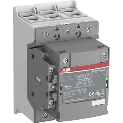
1SFL447001N1311 ABB: The AF140N4-30-11-13 NEMA Contactor is a 3 pole - 1000 V IEC or 600 V UL contactor with double clamp, controlling motors up to 75 kW / 400 V AC (AC-3) or 100 hp / 480 V UL 200 A (AC-1) or 200 A UL general use. Thanks to the AF technology, the contactor has a wide control voltage range (100-250 V, 50/60 Hz and DC), managing large control voltage variations, reducing panel energy consumptions and ensuring distinct operations in unstable networks. Furthermore, surge protection is built-in, offering a compact solution. AF contactors have a block type design, can be easily extended with add-on auxiliary contact blocks and an additional wide range of accessories.
Minimum Order Quantity
1 piece
Customs Tariff Number
85364900
Data Sheet, Technical Information
1SBC100214C0202 - Main catalog Motor protection and control Manual motor starters, contactors and overload relays (PDF) - Edition 2024
Instructions and Manuals
Operating instruction, Contactor, AF(S)116, AF140, AF(S)146
CAD Dimensional Drawing
Information - 2D and 3D files for CAD systems
Product Net Width
90 mm
Product Net Depth / Length
126 mm
Product Net Height
150 mm
Product Net Weight
1.55 kg
Number of Main Contacts NO
3
Number of Main Contacts NC
0
Number of Auxiliary Contacts NO
1
Number of Auxiliary Contacts NC
1
Number of Poles
3P
Standards
IEC 60947-1 / 60947-4-1 and EN 60947-1 / 60947-4-1, UL 508, CSA C22.2 N°14
Rated Operational Voltage
Main Circuit 1000 V
Rated Frequency (f)
Main Circuit 50 / 60 Hz
Conventional Free-air Thermal Current (Ith)
acc. to IEC 60947-4-1, Open Contactors Θ = 40 °C 200 A
Rated Operational Current AC-1 (Ie)
(690 V) 40 °C 200 A | (690 V) 70 °C 160 A
Rated Operational Current AC-3 (Ie)
(415 V) 55 °C 140 A | (440 V) 55 °C 140 A | (500 V) 55 °C 130 A | (690 V) 55 °C 80 A | (380 / 400 V) 55 °C 140 A | (220 / 230 / 240 V) 60 °C 140 A
Rated Operational Current DC-1 (Ie)
(110 V) 2 Poles in Series, 40 °C 160 A | (220 V) 3 Poles in Series, 40 °C 160 A
Rated Operational Current DC-3 (Ie)
(110 V) 2 Poles in Series, 40 °C 160 A | (220 V) 3 Poles in Series, 40 °C 160 A
Rated Operational Current DC-5 (Ie)
(110 V) 2 Poles in Series, 40 °C 160 A | (220 V) 3 Poles in Series, 40 °C 160 A
Rated Operational Power AC-3 (Pe)
(415 V) 75 kW | (440 V) 90 kW | (500 V) 90 kW | (690 V) 75 kW | (380 / 400 V) 75 kW | (220 / 230 / 240 V) 37 kW
Rated Breaking Capacity AC-3
8 x Ie AC-3
Rated Making Capacity AC-3
10 x Ie AC-3
Short-Circuit Protective Devices
gG Type Fuses 315 A
Rated Short-time Withstand Current Low Voltage (Icw)
at 40 °C Ambient Temp, in Free Air, from a Cold State 10 s 1168 A | at 40 °C Ambient Temp, in Free Air, from a Cold State 15 min 200 A | at 40 °C Ambient Temp, in Free Air, from a Cold State 1 min 477 A | at 40 °C Ambient Temp, in Free Air, from a Cold State 1 s 1460 A | at 40 °C Ambient Temp, in Free Air, from a Cold State 30 s 674 A
Maximum Breaking Capacity
cos phi=0.45 (cos phi=0.35 for Ie > 100 A) at 440 V 3000 A | cos phi=0.45 (cos phi=0.35 for Ie > 100 A) at 690 V 1500 A
Rated Insulation Voltage (Ui)
acc. to IEC 60947-4-1 and VDE 0110 (Gr. C) 1000 V
Rated Impulse Withstand Voltage (Uimp)
Main Circuit 8 kV
Maximum Electrical Switching Frequency
(AC-1) 300 cycles per hour | (AC-2 / AC-4) 150 cycles per hour | (AC-3) 300 cycles per hour
Mechanical Durability
5 million
Maximum Mechanical Switching Frequency
300 cycles per hour
Coil Operating Limits
(acc. to IEC 60947-4-1) 0.85 x Uc Min. ... 1.1 x Uc Max. (at θ ≤ 70 °C)
Rated Control Circuit Voltage (Uc)
50 Hz 100...250 V | 60 Hz 100...250 V | DC Operation 100...250 V
Coil Consumption
Holding at Max. Rated Control Circuit Voltage 50 Hz 6 V·A | Holding at Max. Rated Control Circuit Voltage 60 Hz 6 V·A | Holding at Max. Rated Control Circuit Voltage DC 3 W | Pull-in at Max. Rated Control Circuit Voltage 50 Hz 130 V·A | Pull-in at Max. Rated Control Circuit Voltage 60 Hz 130 V·A | Pull-in at Max. Rated Control Circuit Voltage DC 135 W
Power Loss
at Rated Operating Conditions per Pole 9 W
Operate Time
Between Coil De-energization and NO Contact Opening 37 ... 47 ms | Between Coil Energization and NO Contact Closing 25 ... 55 ms
Connecting Capacity Main Circuit
Flexible 2 x 10 ... 70 mm² | Rigid Cu-Cable 2 x 10 ... 95 mm²
Connecting Capacity Auxiliary Circuit
Flexible with Ferrule 2x 0.75 ... 2.5 mm² | Flexible with Insulated Ferrule 2x 0.75 ... 2.5 mm² | Flexible 2x0.75 ... 2.5 mm² | Solid 2x 1 ... 4 mm² | Stranded 2x 1 ... 4 mm²
Connecting Capacity
Flexible 1 x 10 ... 70 mm² | Rigid Cu-Cable 2 x 10 ... 95 mm²
Degree of Protection
acc. to IEC 60529, IEC 60947-1, EN 60529 Coil Terminals IP20 | acc. to IEC 60529, IEC 60947-1, EN 60529 Main Terminals IP00
Tightening Torque
Cable Lug 9 N·m | Main Circuit 8 N·m
Terminal Type
Double Clamp
Product Name
Block Contactor
NEMA Size
4
Ambient Air Temperature
Close to Contactor Fitted with Thermal O/L Relay (0.85 ... 1.1 Uc) -25 ... 50 °C | Close to Contactor without Thermal O/L Relay (0.85 ... 1.1 Uc) -40 ... 70 °C | Close to Contactor for Storage -40 ... 70 °C
Maximum Operating Altitude Permissible
Without Derating 3000 m
Conflict Minerals Reporting Template (CMRT)
CMRT - Conflict Minerals Reporting Template
REACH Declaration
REACH - Letter of Confirmation for block contactors, contactor relays, installation contactors, mini contactors, mini contactor relays, thermal overload relays, electronic overload relays and related accessories
RoHS Information
RoHS II declaration for block contactors, installation contactors, mini contactors, mini contactor relays, thermal overload relays, electronic overload relays and related accessories
RoHS Status
Following EU Directive 2011/65/EU and Amendment 2015/863 July 22, 2019
WEEE B2C / B2B
Business To Business
WEEE Category
5. Small Equipment (No External Dimension More Than 50 cm)
End Of Life Disassembling Instructions
End-of-life instruction - AF(S)116(B)-**(RT) to AF(S)205(B)-**(RT)
A2L Certificate – UL
UL Certificate of Compliance A2L, Contactor, AF116 - AF146
CB Certificate
SEMKO_SE-70479M1
Declaration of Conformity - CE
CE Declaration of Conformity - Contactor - AF116...AF370
UL Certificate
cULus Certificate, Contactor, AF116-30...AF146-30, AFS116-30...AFS146-30
Package Level 1 Units
box 1 piece
Package Level 1 Width
207 mm
Package Level 1 Depth / Length
216 mm
Package Level 1 Height
150 mm
Package Level 1 Gross Weight
1.75 kg
Package Level 1 EAN
7320500543580
Object Classification Code
Q
ETIM 7
EC000066 - Power contactor, AC switching
ETIM 8
EC000066 - Power contactor, AC switching
ETIM 9
EC000066 - Power contactor, AC switching
eClass
V11.0 : 27371003
UNSPSC
39121529
IDEA Granular Category Code (IGCC)
4762 >> Nema Contactors
Feature: AF140N4-30-11-13 employs AF technology with a broad control voltage range (100-250 V, 50/60 Hz and DC). Business Impact: This reduces the number of different control-voltage supplies in panels, cutting inventory and energy waste. Application: ideal for machine panels where supply voltage varies or is not tightly controlled. Feature: Three NO main contacts plus one NO and one NC auxiliary contact, with a double clamp terminal design. Business Impact: ensures robust, vibration-resistant connections and straightforward wiring, lowering installation time and improving reliability. Application: motor starters and automation modules requiring reliable auxiliary signaling. Feature: Built-in surge protection and a compact block design that supports add-on auxiliary contact blocks. Business Impact: protects contacts from voltage spikes, extends service life, and enables scalable control architectures. Application: scalable control schemes for conveyors and pumps in manufacturing lines. Feature: Coil operating limits (0.85 x Uc to 1.1 x Uc) and defined coil consumption (holding and pull-in). Business Impact: predictable coil behavior across temperature ranges; reduces standby heat and energy draw. Application: energy-conscious panel design and predictable maintenance planning. Feature: 1000 V main circuit rating, IP20 coil terminals, IP00 main terminals, and NEMA Size 4 compatibility. Business Impact: broad electrical safety margin, easy external wiring, and seamless integration with standard ABB accessory ecosystems. Application: global machine builds and compliant electrical installations in diverse environments.
Get a Quick Quote for a ABB 1SFL447001N1311
Chat with us on WhatsApp - fast responses guaranteed
Need to speak with someone? We'll call you back within 2 hours during business hours
Interested in ABB 1SFL447001N1311?
Enquire Now
FAQs
Installation is straightforward due to the 2 x 10 ... 70 mm² flexible main-circuit connections and 2 x 0.75 ... 2.5 mm² auxiliary-circuit options. Use the double clamp terminals for secure, vibration-resistant connections, tighten to 8–9 N·m on the main circuit and 9 N·m for lugs. The compact block design supports add-on auxiliary contact blocks, simplifying future expansions without major rewiring.
Main circuit rated voltage is 1000 V with 50/60 Hz; Rated Operational Current AC-3 ranges up to 140 A at 415–690 V depending on configuration; AC-1 current up to 200 A at 690 V. It provides up to 75 kW at 415 V (AC-3) and 90 kW at higher voltages, with a short-circuit withstand of 8 x Ie for AC-3, ensuring safe motor starting.
Yes. The device is designed for AC-3 motor control with high breaking/making capacities and compatible with AC-1 operations for general use. Its 3P main contacts and 1 NO/1 NC auxiliary contact support complex control schemes typical in conveyors and similar automation lines. It also supports rated control-circuit voltages across 100–250 V and a robust mechanical design for frequent cycling.
The AF140N4-30-11-13 meets IEC 60947-1 and IEC 60947-4-1, EN equivalents, UL 508, and CSA C22.2 N°14, with CE declarations. This broad certification set eases global compliance for panel builders and reduces regulatory risk when integrating into multi-region electrical installations.
Long mechanical life (millions of cycles) and built-in surge protection minimize unexpected failures and maintenance downtime. The modular add-on auxiliary blocks support scalable control, lowering BOM changes for future upgrades. Combined with energy-efficient AF technology and wide coil-voltage tolerance, you achieve lower lifecycle costs, faster commissioning, and improved uptime in automated production lines.