ABB 1SFL447001R3100 Block Contactor - AF Technology
Part Number: 1SFL447001R3100
Quick Summary
Block Contactor AF140-30-00-31 enables reliable three-pole motor control for industrial equipment up to 75 kW at 690 V. In environments with voltage fluctuations, dependable coil operation and energy efficiency are common pain points. This AF family delivers a wide control-voltage range and built-in surge protection, backed by CE, UKCA, and UL/CSA certifications. Its compact block design and compatibility with add-on auxiliary blocks simplify panel integration, while broad ratings support flexible motor sizing. That combination lowers total cost of ownership by reducing wiring, energy use, and spare-part complexity.
Product Information
Extended Description
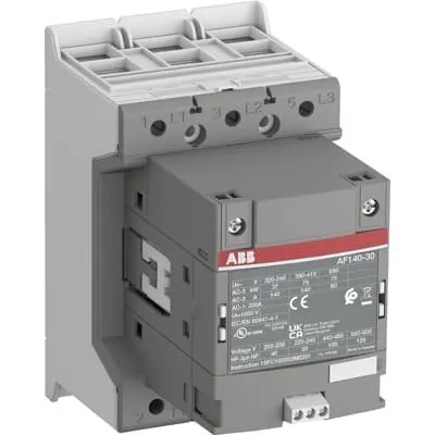
1SFL447001R3100 ABB: The AF140-30-00-31 is a 3 pole - 690 V IEC or 600 V UL contactor with double clamp, controlling motors up to 75 kW / 400 V AC (AC-3) or 100 hp / 480 V UL and switching power circuits up to 200 A (AC-1) or 200 A UL general use. Thanks to the AF technology, the contactor has a wide control voltage range (24-60 V 50/60 Hz and 20-60 V DC), managing large control voltage variations, reducing panel energy consumptions and ensuring distinct operations in unstable networks. Furthermore, surge protection is built-in, offering a compact solution. AF contactors have a block type design, can be easily extended with add-on auxiliary contact blocks and an additional wide range of accessories.
Minimum Order Quantity
1 piece
Customs Tariff Number
8536490099
Data Sheet, Technical Information
1SBC100214C0202 - Main catalog Motor protection and control Manual motor starters, contactors and overload relays (PDF) - Edition 2024
Data Sheet, Technical Information (Part 2)
Contactors and Overload relays guide
Instructions and Manuals
Operating instruction, Contactor, AF(S)116, AF140, AF(S)146
CAD Dimensional Drawing
Information - 2D and 3D files for CAD systems
Product Net Width
90 mm
Product Net Depth / Length
138.5 mm
Product Net Height
150 mm
Product Net Weight
1.55 kg
Number of Main Contacts NO
3
Number of Main Contacts NC
0
Number of Auxiliary Contacts NO
0
Number of Auxiliary Contacts NC
0
Number of Poles
3P
Rated Operational Voltage
Main Circuit 690 V
Rated Frequency (f)
Main Circuit 50 / 60 Hz
Conventional Free-air Thermal Current (Ith)
acc. to IEC 60947-4-1, Open Contactors Θ = 40 °C 200 A
Rated Operational Current AC-1 (Ie)
(690 V) 40 °C 200 A | (690 V) 60 °C 175 A | (690 V) 70 °C 160 A
Rated Operational Current AC-3 (Ie)
(415 V) 60 °C 140 A | (440 V) 60 °C 140 A | (500 V) 60 °C 130 A | (690 V) 60 °C 80 A | (380 / 400 V) 60 °C 140 A | (220 / 230 / 240 V) 60 °C 140 A
Rated Operational Current AC-3e (Ie)
(415 V) 60 °C 140 A | (440 V) 60 °C 140 A | (500 V) 60 °C 130 A | (690 V) 60 °C 80 A | (380 / 400 V) 60 °C 140 A | (220 / 230 / 240 V) 60 °C 140 A
Rated Operational Power AC-3 (Pe)
(415 V) 75 kW | (440 V) 90 kW | (500 V) 90 kW | (690 V) 75 kW | (380 / 400 V) 75 kW | (220 / 230 / 240 V) 37 kW
Rated Operational Power AC-3e (Pe)
(415 V) 75 kW | (440 V) 90 kW | (500 V) 90 kW | (690 V) 75 kW | (380 / 400 V) 75 kW | (220 / 230 / 240 V) 37 kW
Rated Breaking Capacity AC-3
8 x Ie AC-3
Rated Breaking Capacity AC-3e
8.5 x Ie AC-3e
Rated Making Capacity AC-3
10 x Ie AC-3
Rated Making Capacity AC-3e
12 x Ie AC-3e
Rated Short-time Withstand Current Low Voltage (Icw)
at 40 °C Ambient Temp, in Free Air, from a Cold State 10 s 1168 A | at 40 °C Ambient Temp, in Free Air, from a Cold State 15 min 200 A | at 40 °C Ambient Temp, in Free Air, from a Cold State 1 min 477 A | at 40 °C Ambient Temp, in Free Air, from a Cold State 1 s 1460 A | at 40 °C Ambient Temp, in Free Air, from a Cold State 30 s 674 A
Maximum Breaking Capacity
cos phi=0.45 (cos phi=0.35 for Ie > 100 A) at 440 V 3000 A | cos phi=0.45 (cos phi=0.35 for Ie > 100 A) at 690 V 1500 A
Rated Insulation Voltage (Ui)
acc. to IEC 60947-4-1 and VDE 0110 (Gr. C) 1000 V | acc. to UL/CSA 1000 V
Rated Impulse Withstand Voltage (Uimp)
Main Circuit 8 kV
Maximum Electrical Switching Frequency
(AC-1) 300 cycles per hour | (AC-2 / AC-4) 150 cycles per hour | (AC-3) 300 cycles per hour
Mechanical Durability
5 million
Maximum Mechanical Switching Frequency
300 cycles per hour
Coil Operating Limits
(acc. to IEC 60947-4-1) 0.85 x Uc Min. ... 1.1 x Uc Max. (at θ ≤ 70 °C)
Rated Control Circuit Voltage (Uc)
50 Hz 24 ... 60 V | 60 Hz 24...60 V | DC Operation 20...60 V
Coil Consumption
Holding at Max. Rated Control Circuit Voltage 50 Hz 5.5 V·A | Holding at Max. Rated Control Circuit Voltage 50 Hz 2.5 W | Holding at Max. Rated Control Circuit Voltage 60 Hz 5.5 V·A | Holding at Max. Rated Control Circuit Voltage 60 Hz 2.5 W | Holding at Max. Rated Control Circuit Voltage DC 2.5 W | Pull-in at Max. Rated Control Circuit Voltage 50 Hz 225 V·A | Pull-in at Max. Rated Control Circuit Voltage 60 Hz 225 V·A | Pull-in at Max. Rated Control Circuit Voltage DC 210 W
Power Loss
at Rated Operating Conditions AC-1 per Pole 18 W | at Rated Operating Conditions AC-3 per Pole 9 W
Operate Time
Between Coil De-energization and NO Contact Opening 40 ... 70 ms | Between Coil Energization and NO Contact Closing 20 ... 55 ms
Connecting Capacity Main Circuit
Flexible 2 x 10 ... 70 mm² | Rigid Cu-Cable 1 x 10 ... 95 mm²
Connecting Capacity Auxiliary Circuit
Flexible with Ferrule 1x 0.75 ... 2.5 mm² | Flexible with Ferrule 2x 0.75 ... 2.5 mm² | Flexible with Insulated Ferrule 1x 0.75 ... 2.5 mm² | Flexible with Insulated Ferrule 2x 0.75 ... 2.5 mm² | Flexible 1x 0.75 ... 2.5 mm² | Flexible 2x 0.75 ... 2.5 mm² | Solid 1x 1 ... 4 mm² | Solid 2x 1 ... 4 mm² | Stranded 1x 1 ... 4 mm² | Stranded 2x 1 ... 4 mm²
Connecting Capacity
Flexible 1 x 10 ... 70 mm² | Flexible 2 x 10 ... 70 mm² | Rigid Cu-Cable 1 x 10 ... 95 mm²
Wire Stripping Length
Auxiliary Circuit 9 mm | Control Circuit 9 mm
Degree of Protection
acc. to IEC 60529, IEC 60947-1, EN 60529 Coil Terminals IP20 | acc. to IEC 60529, IEC 60947-1, EN 60529 Main Terminals IP00
Recommended Screw Driver
Main Circuit M6 | Control Circuit M3.5
Tightening Torque
Auxiliary Circuit 1 N·m | Cable Lug 9 N·m | Control Circuit 1 N·m | Main Circuit 8 N·m
Terminal Type
Double Clamp
Product Name
Block Contactor
NEMA Size
4
Continuous Current Rating NEMA
135 A
Horsepower Rating NEMA
(200 V AC) Three Phase 40 Hp | (230 V AC) Three Phase 50 Hp | (460 V AC) Three Phase 100 Hp | (575 V AC) Three Phase 100 Hp
Maximum Operating Voltage UL/CSA
Main Circuit 600 V
General Use Rating UL/CSA
(600 V AC) 200 A
Horsepower Rating UL/CSA
(200 ... 208 V AC) Three Phase 40 hp | (220 ... 240 V AC) Three Phase 50 hp | (440 ... 480 V AC) Three Phase 100 hp | (550 ... 600 V AC) Three Phase 125 hp
Tightening Torque UL/CSA
Auxiliary Circuit 9 in·lb | Control Circuit 9 in·lb | Main Circuit 71 in·lb
Full Load Amps Motor Use
(200 ... 208 V AC) Three Phase 120 A | (220 ... 240 V AC) Three Phase 130 A | (440 ... 480 V AC) Three Phase 124 A | (550 ... 600 V AC) Three Phase 125 A
Ambient Air Temperature
Close to Contactor Fitted with Thermal O/L Relay (0.85 ... 1.1 Uc) -25 ... 55 °C | Close to Contactor without Thermal O/L Relay (0.85 ... 1.1 Uc) -40 ... 70 °C | Close to Contactor for Storage -40 ... 70 °C
Maximum Operating Altitude Permissible
Without Derating 3000 m
Conflict Minerals Reporting Template (CMRT)
CMRT - Conflict Minerals Reporting Template
REACH Declaration
REACH - Letter of Confirmation for block contactors, contactor relays, installation contactors, mini contactors, mini contactor relays, thermal overload relays, electronic overload relays and related accessories
RoHS Information
RoHS II declaration for block contactors, installation contactors, mini contactors, mini contactor relays, thermal overload relays, electronic overload relays and related accessories
RoHS Status
Following EU Directive 2011/65/EU and Amendment 2015/863 July 22, 2019
Toxic Substances Control Act - TSCA
Toxic Substances Control Act (TSCA) declaration for Contactors
WEEE B2C / B2B
Business To Business
WEEE Category
5. Small Equipment (No External Dimension More Than 50 cm)
ABB EcoSolutions
Yes
ABB Site Meeting Group Waste To Landfill Target
Non-hazardous waste is sent to a landfill, where there is no alternative option available within 100km of a facility
End Of Life Disassembling Instructions
End-of-life instruction - AF(S)116(B)-**(RT) to AF(S)205(B)-**(RT)
Environmental Product Declaration - EPD
Environmental Product Declaration, AF(S)116-AF(S)146 (SE) Contactors
Improved Energy Efficiency for Customers
Product Efficiency - Product requires less energy to operate compared to similar product on market or older products from the same line
Recyclability Rate of the Product acc. to EN45555
Design for Closing Resource Loops - Standard EN45555 - 87.8 %
Sustainable Material Content in Product (wt. %)
Recycled Metal - 37 %
A2L Certificate – UL
UL Certificate of Compliance A2L, Contactor, AF116 - AF146
Declaration of Conformity - CE
CE Declaration of Conformity - Contactor - AF116...AF370
Declaration of Conformity - UKCA
UK Declaration of Conformity - Contactors >100A
UL Certificate
cULus Certificate, Contactor, AF116-30...AF146-30, AFS116-30...AFS146-30
Package Level 1 Units
box 1 piece
Package Level 1 Width
207 mm
Package Level 1 Depth / Length
216 mm
Package Level 1 Height
150 mm
Package Level 1 Gross Weight
1.75 kg
Package Level 1 EAN
7320500560389
Object Classification Code
Q
ETIM 7
EC000066 - Power contactor, AC switching
ETIM 8
EC000066 - Power contactor, AC switching
ETIM 9
EC000066 - Power contactor, AC switching
eClass
V11.0 : 27371003
UNSPSC
39121529
IDEA Granular Category Code (IGCC)
4758 >> Iec Contactors
Wide coil-voltage range and AF technology provide resilience to voltage swings in demanding applications. With 24-60 V AC or 20-60 V DC control options, the coil tolerates supply variations, reducing nuisance tripping and panel energy losses in manufacturing lines and process equipment. The built-in surge protection minimizes external protection hardware, boosting reliability in harsh electrical environments. The compact block design supports easy installation and serviceability, while the option to add auxiliary contact blocks enables future expansion without a full replacement. Rated for main circuits up to 690 V and 3 poles, it delivers up to 140 A AC-3 and 75 kW AC-3p performance, lowering life-cycle costs. The double clamp terminals and clearly defined torque specs simplify wiring and maintenance, with IP20 coil and IP00 main terminal protection.
Get a Quick Quote for a ABB 1SFL447001R3100
Chat with us on WhatsApp - fast responses guaranteed
Need to speak with someone? We'll call you back within 2 hours during business hours
Interested in ABB 1SFL447001R3100?
Enquire Now
FAQs
The AF140 series uses a block design with double clamp main terminals and a straightforward wiring scheme. Use Flexible or Solid copper cables within 10–70 mm² for the main circuit and 0.75–4 mm² for auxiliary or control circuits. Tighten main circuit connections to 8 N·m, auxiliary and control to 1 N·m, and preserve IP00 main terminal protection with proper enclosure and strain relief. The product supports 24–60 V AC, 20–60 V DC control signals, simplifying panel inventories.
The device supports a broad coil range: 24–60 V AC or 20–60 V DC. This tolerance reduces misoperation and wiring complexity in systems with fluctuating supply, minimizes the need for separate coil variants, and improves reliability in panels facing voltage swings or long cable runs.
Yes. It handles up to 75 kW at 415–690 V (AC-3) with main-current ratings up to 140 A at 60 °C and 80 A at 690 V for AC-3, plus 200 A AC-1 at 690 V. It provides 8 xIe breaking capacity for AC-3 and 8.5 xIe for AC-3e, ensuring robust switching for motors in pump, conveyor, and compressor applications.
The AF140-30-00-31 carries CE and UKCA declarations, UL/cULus listings, and RoHS/REACH compliance. These certifications support safe, compliant operation across European, UK, and North American markets, with UL A2L certification where applicable for system-level electrification.
Long mechanical life (up to 5 million cycles) and built‑in surge protection reduce maintenance and spare-parts costs. Energy-efficient AF technology lowers panel power consumption, while easy expansion via add-on auxiliary blocks minimizes future capital expenditure when upgrading lines or adding control circuits.