ABB 1SFL447001R4300 Block Contactor - UL/CSA 690 V
Part Number: 1SFL447001R4300
Quick Summary
ABB 1SFL447001R4300 block contactor is a high-capacity switching device designed for motor control in industrial automation. Engineers routinely face energy waste and unreliable starts in networks with voltage fluctuations; this unit delivers precise operation and built-in surge protection to stabilize panels. It carries CE and UKCA declarations, along with UL/CSA certification, ensuring broad regulatory compliance and safe operation across markets. With AF technology, it minimizes energy use and offers a compact footprint. The block design supports easy extension with auxiliary contact blocks and a wide range of accessories, helping plants scale without rewiring while maintaining reliability and performance.
Product Information
Extended Description
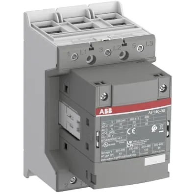
1SFL447001R4300 ABB: The AF140-30-00-43 is a 3 pole - 690 V IEC or 600 V UL contactor with double clamp, controlling motors up to 75 kW / 400 V AC (AC-3) or 100 hp / 480 V UL and switching power circuits up to 200 A (AC-1) or 200 A UL general use. Thanks to the AF technology, the contactor has a control voltage range (220-240 V 50/60 Hz),faster operation time, reducing panel energy consumptions and ensuring distinct operations in unstable networks. Furthermore, surge protection is built-in, offering a compact solution. AF contactors have a block type design, can be easily extended with add-on auxiliary contact blocks and an additional wide range of accessories.
Minimum Order Quantity
1 piece
Customs Tariff Number
8536490099
Data Sheet, Technical Information
1SBC100214C0202 - Main catalog Motor protection and control Manual motor starters, contactors and overload relays (PDF) - Edition 2024
Data Sheet, Technical Information (Part 2)
Contactors and Overload relays guide
Instructions and Manuals
Operating instruction, Contactor, AF(S)116, AF140, AF(S)146
CAD Dimensional Drawing
Information - 2D and 3D files for CAD systems
Product Net Width
90 mm
Product Net Depth / Length
126 mm
Product Net Height
150 mm
Product Net Weight
1.55 kg
Number of Main Contacts NO
3
Number of Main Contacts NC
0
Number of Auxiliary Contacts NO
0
Number of Auxiliary Contacts NC
0
Number of Poles
3P
Rated Operational Voltage
Main Circuit 690 V
Rated Frequency (f)
Main Circuit 50 / 60 Hz
Conventional Free-air Thermal Current (Ith)
acc. to IEC 60947-4-1, Open Contactors Θ = 40 °C 200 A
Rated Operational Current AC-1 (Ie)
(690 V) 40 °C 200 A | (690 V) 60 °C 175 A | (690 V) 70 °C 160 A
Rated Operational Current AC-3 (Ie)
(415 V) 60 °C 140 A | (440 V) 60 °C 140 A | (500 V) 60 °C 130 A | (690 V) 60 °C 80 A | (380 / 400 V) 60 °C 140 A | (220 / 230 / 240 V) 60 °C 140 A
Rated Operational Current AC-3e (Ie)
(415 V) 60 °C 140 A | (440 V) 60 °C 140 A | (500 V) 60 °C 130 A | (690 V) 60 °C 80 A | (380 / 400 V) 60 °C 140 A | (220 / 230 / 240 V) 60 °C 140 A
Rated Operational Power AC-3 (Pe)
(415 V) 75 kW | (440 V) 90 kW | (500 V) 90 kW | (690 V) 75 kW | (380 / 400 V) 75 kW | (220 / 230 / 240 V) 37 kW
Rated Operational Power AC-3e (Pe)
(415 V) 75 kW | (440 V) 90 kW | (500 V) 90 kW | (690 V) 75 kW | (380 / 400 V) 75 kW | (220 / 230 / 240 V) 37 kW
Rated Breaking Capacity AC-3
8 x Ie AC-3
Rated Breaking Capacity AC-3e
8.5 x Ie AC-3e
Rated Making Capacity AC-3
10 x Ie AC-3
Rated Making Capacity AC-3e
12 x Ie AC-3e
Rated Short-time Withstand Current Low Voltage (Icw)
at 40 °C Ambient Temp, in Free Air, from a Cold State 10 s 1168 A | at 40 °C Ambient Temp, in Free Air, from a Cold State 15 min 200 A | at 40 °C Ambient Temp, in Free Air, from a Cold State 1 min 477 A | at 40 °C Ambient Temp, in Free Air, from a Cold State 1 s 1460 A | at 40 °C Ambient Temp, in Free Air, from a Cold State 30 s 674 A
Maximum Breaking Capacity
cos phi=0.45 (cos phi=0.35 for Ie > 100 A) at 440 V 3000 A | cos phi=0.45 (cos phi=0.35 for Ie > 100 A) at 690 V 1500 A
Rated Insulation Voltage (Ui)
acc. to IEC 60947-4-1 and VDE 0110 (Gr. C) 1000 V | acc. to UL/CSA 1000 V
Rated Impulse Withstand Voltage (Uimp)
Main Circuit 8 kV
Maximum Electrical Switching Frequency
(AC-1) 300 cycles per hour | (AC-2 / AC-4) 150 cycles per hour | (AC-3) 300 cycles per hour
Mechanical Durability
5 million
Maximum Mechanical Switching Frequency
300 cycles per hour
Rated Control Circuit Voltage (Uc)
50 Hz 220 ... 240 V | 60 Hz 220 ... 240 V
Coil Consumption
Holding at Max. Rated Control Circuit Voltage 50 Hz 8 V·A | Holding at Max. Rated Control Circuit Voltage 50 Hz 2.5 W | Holding at Max. Rated Control Circuit Voltage 60 Hz 8 V·A | Holding at Max. Rated Control Circuit Voltage 60 Hz 2.5 W | Pull-in at Max. Rated Control Circuit Voltage 50 Hz 130 V·A | Pull-in at Max. Rated Control Circuit Voltage 60 Hz 130 V·A
Power Loss
at Rated Operating Conditions AC-1 per Pole 18 W | at Rated Operating Conditions AC-3 per Pole 9 W
Operate Time
Between Coil De-energization and NO Contact Opening 15 ... 20 ms | Between Coil Energization and NO Contact Closing 20 ... 35 ms
Connecting Capacity Main Circuit
Flexible 2 x 10 ... 70 mm² | Rigid Cu-Cable 1 x 10 ... 95 mm²
Connecting Capacity Auxiliary Circuit
Flexible with Ferrule 1x 0.75 ... 2.5 mm² | Flexible with Ferrule 2x 0.75 ... 2.5 mm² | Flexible with Insulated Ferrule 1x 0.75 ... 2.5 mm² | Flexible with Insulated Ferrule 2x 0.75 ... 2.5 mm² | Flexible 1x 0.75 ... 2.5 mm² | Flexible 2x 0.75 ... 2.5 mm² | Solid 1x 1 ... 4 mm² | Solid 2x 1 ... 4 mm² | Stranded 1x 1 ... 4 mm² | Stranded 2x 1 ... 4 mm²
Connecting Capacity
Flexible 1 x 10 ... 70 mm² | Flexible 2 x 10 ... 70 mm² | Rigid Cu-Cable 1 x 10 ... 95 mm²
Wire Stripping Length
Auxiliary Circuit 9 mm | Control Circuit 9 mm
Degree of Protection
acc. to IEC 60529, IEC 60947-1, EN 60529 Coil Terminals IP20 | acc. to IEC 60529, IEC 60947-1, EN 60529 Main Terminals IP00
Recommended Screw Driver
Main Circuit M6 | Control Circuit M3.5
Tightening Torque
Auxiliary Circuit 1 N·m | Cable Lug 9 N·m | Control Circuit 1 N·m | Main Circuit 8 N·m
Terminal Type
Double Clamp
Product Name
Block Contactor
NEMA Size
4
Continuous Current Rating NEMA
135 A
Horsepower Rating NEMA
(200 V AC) Three Phase 40 Hp | (230 V AC) Three Phase 50 Hp | (460 V AC) Three Phase 100 Hp | (575 V AC) Three Phase 100 Hp
Maximum Operating Voltage UL/CSA
Main Circuit 600 V
General Use Rating UL/CSA
(600 V AC) 200 A
Horsepower Rating UL/CSA
(200 ... 208 V AC) Three Phase 40 hp | (220 ... 240 V AC) Three Phase 50 hp | (440 ... 480 V AC) Three Phase 100 hp | (550 ... 600 V AC) Three Phase 125 hp
Tightening Torque UL/CSA
Auxiliary Circuit 9 in·lb | Control Circuit 9 in·lb | Main Circuit 71 in·lb
Full Load Amps Motor Use
(200 ... 208 V AC) Three Phase 120 A | (220 ... 240 V AC) Three Phase 130 A | (440 ... 480 V AC) Three Phase 124 A | (550 ... 600 V AC) Three Phase 125 A
Ambient Air Temperature
Close to Contactor Fitted with Thermal O/L Relay (0.85 ... 1.1 Uc) -25 ... 55 °C | Close to Contactor without Thermal O/L Relay (0.85 ... 1.1 Uc) -40 ... 70 °C | Close to Contactor for Storage -40 ... 70 °C
Maximum Operating Altitude Permissible
Without Derating 3000 m
Conflict Minerals Reporting Template (CMRT)
CMRT - Conflict Minerals Reporting Template
REACH Declaration
REACH - Letter of Confirmation for block contactors, contactor relays, installation contactors, mini contactors, mini contactor relays, thermal overload relays, electronic overload relays and related accessories
RoHS Information
RoHS II declaration for block contactors, installation contactors, mini contactors, mini contactor relays, thermal overload relays, electronic overload relays and related accessories
RoHS Status
Following EU Directive 2011/65/EU and Amendment 2015/863 July 22, 2019
Toxic Substances Control Act - TSCA
Toxic Substances Control Act (TSCA) declaration for Contactors
WEEE B2C / B2B
Business To Business
WEEE Category
5. Small Equipment (No External Dimension More Than 50 cm)
ABB EcoSolutions
Yes
ABB Site Meeting Group Waste To Landfill Target
Non-hazardous waste is sent to a landfill, where there is no alternative option available within 100km of a facility
End Of Life Disassembling Instructions
End-of-life instruction - AF(S)116(B)-**(RT) to AF(S)205(B)-**(RT)
Environmental Product Declaration - EPD
Environmental Product Declaration, AF(S)116-AF(S)146 (SE) Contactors
Improved Energy Efficiency for Customers
Product Efficiency - Product requires less energy to operate compared to similar product on market or older products from the same line
Recyclability Rate of the Product acc. to EN45555
Design for Closing Resource Loops - Standard EN45555 - 87.8 %
Sustainable Material Content in Product (wt. %)
Recycled Metal - 37 %
A2L Certificate – UL
UL Certificate of Compliance A2L, Contactor, AF116 - AF146
Declaration of Conformity - CE
CE Declaration of Conformity - Contactor - AF116...AF370
Declaration of Conformity - UKCA
UK Declaration of Conformity - Contactors >100A
UL Certificate
cULus Certificate, Contactor, AF116-30...AF146-30, AFS116-30...AFS146-30
Package Level 1 Units
box 1 piece
Package Level 1 Width
207 mm
Package Level 1 Depth / Length
216 mm
Package Level 1 Height
150 mm
Package Level 1 Gross Weight
1.75 kg
Package Level 1 EAN
7320500560617
Object Classification Code
Q
ETIM 7
EC000066 - Power contactor, AC switching
ETIM 8
EC000066 - Power contactor, AC switching
ETIM 9
EC000066 - Power contactor, AC switching
eClass
V11.0 : 27371003
UNSPSC
39121529
IDEA Granular Category Code (IGCC)
4758 >> Iec Contactors
Feature: 3-pole main circuit rated to 690 V and 200 A AC-1 with 140 A AC-3 at 415 V. Business Impact: Enables reliable motor control for midsize to large loads (up to 75 kW), reducing panel space and wiring complexity. Application: Ideal for conveyors, pumps, and general machine drives where duty cycles demand consistent switching. Feature: AF technology with surge protection and precise control over voltage fluctuations. Business Impact: Lower energy consumption in idle and hold states translates to measurable energy savings and cooler panel operation. Application: Suitable for networks with unstable supply in manufacturing lines and packaging equipment. Feature: Coil voltage range 220–240 V at 50/60 Hz with defined hold and pull-in currents. Business Impact: Simplifies control circuit design, improves reliability, and minimizes coil heating in continuous operation. Application: Compatible with standard control panels and existing control circuits.Feature: Double Clamp terminals and flexible conductor options. Business Impact: Improves installation speed and reduces torque variance, cutting commissioning time and maintenance downtime. Application: Fast field terminations for main and auxiliary circuits in new builds or retrofit projects.Feature: Robust mechanical durability and high breaking capacity ratings. Business Impact: Extends equipment life and supports demanding startup transients, lowering lifecycle costs. Application: Critical on heavy-start applications like fans, pumps, and presses in industrial environments.
Get a Quick Quote for a ABB 1SFL447001R4300
Chat with us on WhatsApp - fast responses guaranteed
Need to speak with someone? We'll call you back within 2 hours during business hours
Interested in ABB 1SFL447001R4300?
Enquire Now
FAQs
This unit uses a double clamp terminal design and supports add-on auxiliary contact blocks. With a 3P 690 V main circuit and coil range of 220–240 V at 50/60 Hz, it integrates into standard control panels and allows straightforward expansion using ABB AF accessories, minimizing rework and downtime during upgrades.
At 690 V, the Rated Operational Current AC-3 is 80 A (60 °C) and 140 A for 415 V variants. This equates to a rated operational power of up to 75 kW at 415 V, enabling reliable control of mid-to-large motors while maintaining safe switching performance under typical IEC 60947-4-1 conditions.
Yes. The device supports motor control up to 75 kW in the AC-3 rating at appropriate voltages (e.g., 415 V). It also provides robust short-time withstand characteristics and a solid 8 kV impulse withstand, making it suitable for demanding conveyor, pump, and process equipment duties.
The product features CE and UKCA declarations, plus UL/CSA certification for broad market acceptance. It also aligns with RoHS and REACH regulations, with UL A2L considerations and a CULus listing for safe use in North America.
AF technology reduces energy consumption in hold and standby states, contributing to lower operating costs and cooler panel environments. The device's mechanical durability is up to 5 million cycles, supporting longer service life and reduced maintenance interruptions on critical motor control applications.