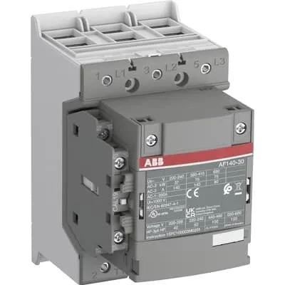
ABB AF140-30-11-43 Contactor - CE/UL/CSA - 690 V / 200 A
Part Number: 1SFL447001R4311
Quick Summary
ABB AF140-30-11-43 Contactor is a 3-pole motor starter designed for reliable control of medium to high power motors in automated panels. In real-world installations, voltage dips and switching transients can cause nuisance trips; AF technology delivers faster coil pull-in and stable operation even in unstable networks, reducing wear and energy waste. This device ships with built-in surge protection and a compact block design that saves panel space and simplifies wiring. The unit carries CE, UKCA, and UL/CSA certifications, plus RoHS and REACH declarations, ensuring global compliance across markets. For system integrators, the AF140-30-11-43 provides easy add-on expansion with auxiliary contacts and accessible accessories, improving uptime and maintenance planning while meeting demanding industrial standards.
Product Information
Extended Description
1SFL447001R4311 ABB: The AF140-30-11-43 is a 3 pole - 690 V IEC or 600 V UL contactor with double clamp, controlling motors up to 75 kW / 400 V AC (AC-3) or 100 hp / 480 V UL and switching power circuits up to 200 A (AC-1) or 200 A UL general use. Thanks to the AF technology, the contactor has a control voltage range (220-240 V 50/60 Hz),faster operation time, reducing panel energy consumptions and ensuring distinct operations in unstable networks. Furthermore, surge protection is built-in, offering a compact solution. AF contactors have a block type design, can be easily extended with add-on auxiliary contact blocks and an additional wide range of accessories.
Minimum Order Quantity
1 piece
Customs Tariff Number
8536490099
Data Sheet, Technical Information
1SBC100214C0202 - Main catalog Motor protection and control Manual motor starters, contactors and overload relays (PDF) - Edition 2024
Data Sheet, Technical Information (Part 2)
Contactors and Overload relays guide
Instructions and Manuals
Operating instruction, Contactor, AF(S)116, AF140, AF(S)146
CAD Dimensional Drawing
Information - 2D and 3D files for CAD systems
Product Net Width
90 mm
Product Net Depth / Length
126 mm
Product Net Height
150 mm
Product Net Weight
1.55 kg
Number of Main Contacts NO
3
Number of Main Contacts NC
0
Number of Auxiliary Contacts NO
1
Number of Auxiliary Contacts NC
1
Number of Poles
3P
Rated Operational Voltage
Main Circuit 690 V
Rated Frequency (f)
Main Circuit 50 / 60 Hz
Conventional Free-air Thermal Current (Ith)
acc. to IEC 60947-4-1, Open Contactors Θ = 40 °C 200 A
Rated Operational Current AC-1 (Ie)
(690 V) 40 °C 200 A | (690 V) 60 °C 175 A | (690 V) 70 °C 160 A
Rated Operational Current AC-3 (Ie)
(415 V) 60 °C 140 A | (440 V) 60 °C 140 A | (500 V) 60 °C 130 A | (690 V) 60 °C 80 A | (380 / 400 V) 60 °C 140 A | (220 / 230 / 240 V) 60 °C 140 A
Rated Operational Current AC-3e (Ie)
(415 V) 60 °C 140 A | (440 V) 60 °C 140 A | (500 V) 60 °C 130 A | (690 V) 60 °C 80 A | (380 / 400 V) 60 °C 140 A | (220 / 230 / 240 V) 60 °C 140 A
Rated Operational Power AC-3 (Pe)
(415 V) 75 kW | (440 V) 90 kW | (500 V) 90 kW | (690 V) 75 kW | (380 / 400 V) 75 kW | (220 / 230 / 240 V) 37 kW
Rated Operational Power AC-3e (Pe)
(415 V) 75 kW | (440 V) 90 kW | (500 V) 90 kW | (690 V) 75 kW | (380 / 400 V) 75 kW | (220 / 230 / 240 V) 37 kW
Rated Breaking Capacity AC-3
8 x Ie AC-3
Rated Breaking Capacity AC-3e
8.5 x Ie AC-3e
Rated Making Capacity AC-3
10 x Ie AC-3
Rated Making Capacity AC-3e
12 x Ie AC-3e
Rated Short-time Withstand Current Low Voltage (Icw)
at 40 °C Ambient Temp, in Free Air, from a Cold State 10 s 1168 A | at 40 °C Ambient Temp, in Free Air, from a Cold State 15 min 200 A | at 40 °C Ambient Temp, in Free Air, from a Cold State 1 min 477 A | at 40 °C Ambient Temp, in Free Air, from a Cold State 1 s 1460 A | at 40 °C Ambient Temp, in Free Air, from a Cold State 30 s 674 A
Maximum Breaking Capacity
cos phi=0.45 (cos phi=0.35 for Ie > 100 A) at 440 V 3000 A | cos phi=0.45 (cos phi=0.35 for Ie > 100 A) at 690 V 1500 A
Rated Insulation Voltage (Ui)
acc. to IEC 60947-4-1 and VDE 0110 (Gr. C) 1000 V | acc. to UL/CSA 1000 V
Rated Impulse Withstand Voltage (Uimp)
Main Circuit 8 kV
Maximum Electrical Switching Frequency
(AC-1) 300 cycles per hour | (AC-2 / AC-4) 150 cycles per hour | (AC-3) 300 cycles per hour
Mechanical Durability
5 million
Maximum Mechanical Switching Frequency
300 cycles per hour
Rated Control Circuit Voltage (Uc)
50 Hz 220 ... 240 V | 60 Hz 220 ... 240 V
Coil Consumption
Holding at Max. Rated Control Circuit Voltage 50 Hz 8 V·A | Holding at Max. Rated Control Circuit Voltage 50 Hz 2.5 W | Holding at Max. Rated Control Circuit Voltage 60 Hz 8 V·A | Holding at Max. Rated Control Circuit Voltage 60 Hz 2.5 W | Pull-in at Max. Rated Control Circuit Voltage 50 Hz 130 V·A | Pull-in at Max. Rated Control Circuit Voltage 60 Hz 130 V·A
Power Loss
at Rated Operating Conditions AC-1 per Pole 18 W | at Rated Operating Conditions AC-3 per Pole 9 W
Operate Time
Between Coil De-energization and NO Contact Opening 15 ... 20 ms | Between Coil Energization and NO Contact Closing 20 ... 35 ms
Connecting Capacity Main Circuit
Flexible 2 x 10 ... 70 mm² | Rigid Cu-Cable 1 x 10 ... 95 mm²
Connecting Capacity Auxiliary Circuit
Flexible with Ferrule 1x 0.75 ... 2.5 mm² | Flexible with Ferrule 2x 0.75 ... 2.5 mm² | Flexible with Insulated Ferrule 1x 0.75 ... 2.5 mm² | Flexible with Insulated Ferrule 2x 0.75 ... 2.5 mm² | Flexible 1x 0.75 ... 2.5 mm² | Flexible 2x 0.75 ... 2.5 mm² | Solid 1x 1 ... 4 mm² | Solid 2x 1 ... 4 mm² | Stranded 1x 1 ... 4 mm² | Stranded 2x 1 ... 4 mm²
Connecting Capacity
Flexible 1 x 10 ... 70 mm² | Flexible 2 x 10 ... 70 mm² | Rigid Cu-Cable 1 x 10 ... 95 mm²
Wire Stripping Length
Auxiliary Circuit 9 mm | Control Circuit 9 mm
Degree of Protection
acc. to IEC 60529, IEC 60947-1, EN 60529 Coil Terminals IP20 | acc. to IEC 60529, IEC 60947-1, EN 60529 Main Terminals IP00
Recommended Screw Driver
Main Circuit M6 | Control Circuit M3.5
Tightening Torque
Auxiliary Circuit 1 N·m | Cable Lug 9 N·m | Control Circuit 1 N·m | Main Circuit 8 N·m
Terminal Type
Double Clamp
Product Name
Block Contactor
NEMA Size
4
Continuous Current Rating NEMA
135 A
Horsepower Rating NEMA
(200 V AC) Three Phase 40 Hp | (230 V AC) Three Phase 50 Hp | (460 V AC) Three Phase 100 Hp | (575 V AC) Three Phase 100 Hp
Maximum Operating Voltage UL/CSA
Main Circuit 600 V
General Use Rating UL/CSA
(600 V AC) 200 A
Horsepower Rating UL/CSA
(200 ... 208 V AC) Three Phase 40 hp | (220 ... 240 V AC) Three Phase 50 hp | (440 ... 480 V AC) Three Phase 100 hp | (550 ... 600 V AC) Three Phase 125 hp
Tightening Torque UL/CSA
Auxiliary Circuit 9 in·lb | Control Circuit 9 in·lb | Main Circuit 71 in·lb
Full Load Amps Motor Use
(200 ... 208 V AC) Three Phase 120 A | (220 ... 240 V AC) Three Phase 130 A | (440 ... 480 V AC) Three Phase 124 A | (550 ... 600 V AC) Three Phase 125 A
Ambient Air Temperature
Close to Contactor Fitted with Thermal O/L Relay (0.85 ... 1.1 Uc) -25 ... 55 °C | Close to Contactor without Thermal O/L Relay (0.85 ... 1.1 Uc) -40 ... 70 °C | Close to Contactor for Storage -40 ... 70 °C
Maximum Operating Altitude Permissible
Without Derating 3000 m
Conflict Minerals Reporting Template (CMRT)
CMRT - Conflict Minerals Reporting Template
REACH Declaration
REACH - Letter of Confirmation for block contactors, contactor relays, installation contactors, mini contactors, mini contactor relays, thermal overload relays, electronic overload relays and related accessories
RoHS Information
RoHS II declaration for block contactors, installation contactors, mini contactors, mini contactor relays, thermal overload relays, electronic overload relays and related accessories
RoHS Status
Following EU Directive 2011/65/EU and Amendment 2015/863 July 22, 2019
Toxic Substances Control Act - TSCA
Toxic Substances Control Act (TSCA) declaration for Contactors
WEEE B2C / B2B
Business To Business
WEEE Category
5. Small Equipment (No External Dimension More Than 50 cm)
ABB EcoSolutions
Yes
ABB Site Meeting Group Waste To Landfill Target
Non-hazardous waste is sent to a landfill, where there is no alternative option available within 100km of a facility
End Of Life Disassembling Instructions
End-of-life instruction - AF(S)116(B)-**(RT) to AF(S)205(B)-**(RT)
Environmental Product Declaration - EPD
Environmental Product Declaration, AF(S)116-AF(S)146 (SE) Contactors
Improved Energy Efficiency for Customers
Product Efficiency - Product requires less energy to operate compared to similar product on market or older products from the same line
Recyclability Rate of the Product acc. to EN45555
Design for Closing Resource Loops - Standard EN45555 - 87.8 %
Sustainable Material Content in Product (wt. %)
Recycled Metal - 37 %
A2L Certificate – UL
UL Certificate of Compliance A2L, Contactor, AF116 - AF146
Declaration of Conformity - CE
CE Declaration of Conformity - Contactor - AF116...AF370
Declaration of Conformity - UKCA
UK Declaration of Conformity - Contactors >100A
UL Certificate
cULus Certificate, Contactor, AF116-30...AF146-30, AFS116-30...AFS146-30
Package Level 1 Units
box 1 piece
Package Level 1 Width
207 mm
Package Level 1 Depth / Length
216 mm
Package Level 1 Height
150 mm
Package Level 1 Gross Weight
1.75 kg
Package Level 1 EAN
7320500560624
Object Classification Code
Q
ETIM 7
EC000066 - Power contactor, AC switching
ETIM 8
EC000066 - Power contactor, AC switching
ETIM 9
EC000066 - Power contactor, AC switching
eClass
V11.0 : 27371003
UNSPSC
39121529
IDEA Granular Category Code (IGCC)
4758 >> Iec Contactors
AF technology with a 50/60 Hz coil range 220–240 V delivers faster pull-in and reduced panel energy use, lowering heat generation and improving overall drive efficiency. Business impact: lower energy costs, shorter startup times, and improved motor life in automation applications such as conveyors and pumps. Application: install in 3-phase motor circuits up to 75 kW at 400–415 V while maintaining precise control. Built-in surge protection and a compact AF block design minimize external components, save cabinet space, and simplify wiring—reducing installation time and potential fault sources. Business impact: accelerated commissioning and lower wiring errors in control panels. Application: ideal for retrofit projects and new builds where space is at a premium. The 3-pole main circuit rated at 690 V with 200 A Ic and 140 A Ie (AC-3) at 60 °C ensures robust motor switching; 8 × Ie AC-3e breaking capacity supports heavy loads. Application: reliable protection for high-inertia motors in manufacturing lines. The AF140-30-11-43 features flexible main circuit connections: 2 × 10–70 mm² or 1 × 10–95 mm², facilitating both flexible and rigid wiring. Business impact: simplified field wiring and faster terminations during panel assembly. Application: panel builders and maintenance teams benefit from reduced install time and cleaner cable management. With an auxiliary contact pair (NO/NC), you can implement interlocks and feedback loops without extra parts. Business impact: improved safety interlocks and process monitoring. Application: upgradable with add-on auxiliary blocks for scalable control schemes. The device’s durability (up to 5 million mechanical cycles) ensures long service life in demanding environments, while mechanical and electrical ratings support reliable operation across temperature and altitude ranges. Application: industrial environments with variable loads and ambient conditions. Finally, its compliance footprint—CE, UKCA, UL/CSA, RoHS/REACH, and EM compliance documentation—supports global deployments and lifecycle planning. Business impact: easier audits, market readiness, and lower risk of non-compliance across facilities.
Get a Quick Quote for a ABB 1SFL447001R4311
Chat with us on WhatsApp - fast responses guaranteed
Need to speak with someone? We'll call you back within 2 hours during business hours
Interested in ABB 1SFL447001R4311?
Enquire Now
FAQs
Wire the Main Circuit using flexible 2 x 10–70 mm² or rigid Cu cable 1 x 10–95 mm² via the double clamp terminals. The coil requires 220–240 V at 50/60 Hz. Use the 3 NO main contacts for the motor circuit and the 1 NO/1 NC auxiliary contacts for feedback or interlocking. Maintain proper stripping lengths (9 mm for auxiliary and control circuits) and observe IP20/IP00 protection ratings on coil vs. main terminations.
For AC-1 at 690 V, Ie is 200 A at 40 °C, 175 A at 60 °C, and 160 A at 70 °C. For AC-3 at 415–440 V, Ie is 140 A at 60 °C and 140 A at 60 °C for 380/400 V, with 130 A at 60 °C for 500 V and 80 A at 60 °C for 690 V. These values reflect performance across typical industrial ambient ranges, ensuring reliable motor switching with your load profile.
Yes. The AF140-30-11-43 delivers AC-3 power ratings around 75 kW at 415 V and 75 kW at 380/400 V, with supporting Ie of up to 140 A in several configurations. Its 690 V main circuit and 3-pole design are chosen to handle high-inertia loads common in pumps, fans, and conveyors, making it a solid match for many 75 kW class drives.
The AF140-30-11-43 carries CE and UKCA declarations, UL/CSA listings for general use, and RoHS/REACH compliance. It also aligns with UL A2L certification and related environmental/product declarations. This broad certification footprint supports global procurement, regulatory audits, and sustainable product stewardship across markets.
Key ROI drivers include built-in surge protection reducing external hardware and energy losses (18 W per pole in AC-1, 9 W in AC-3), long mechanical durability (up to 5 million cycles), and compatibility with add-on auxiliary blocks for scalable control. Installation benefits come from double clamp terminals and flexible wiring (2 x 10–70 mm² or 1 x 10–95 mm²), saving time and labor in both new builds and retrofit projects.