ABB 1SFL447002R3200 Block Contactor - UL/CSA
Part Number: 1SFL447002R3200
Quick Summary
Block Contactor 1SFL447002R3200 enables reliable 3-phase motor control in industrial automation and panel-building environments. Engineers rely on devices that deliver consistent switching under variable supply conditions without sacrificing compactness. This model addresses voltage fluctuations, surge events, and space constraints by combining AF technology with a wide control voltage range. It carries CE and UL/CSA listings, plus UKCA where applicable, and RoHS/REACH declarations to streamline regulatory compliance. The coil is protected with IP20 terminals while mains connections retain IP00 protection, and built-in surge protection enhances reliability in demanding installations. With the ability to extend with auxiliary contact blocks, this solution reduces panel revisions, minimizes energy waste, and accelerates installation in modern machines that demand robust performance.
Product Information
Extended Description
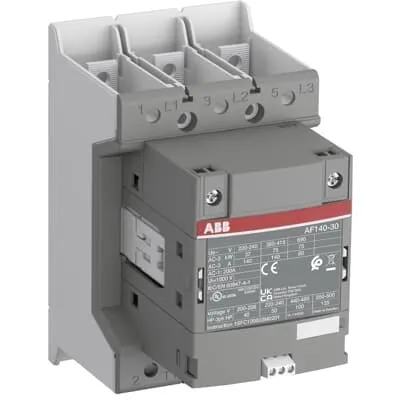
1SFL447002R3200 ABB: The AF140-30-00B-32 is a 3 pole - 690 V IEC or 600 V UL contactor with Main Circuit Bars, controlling motors up to 75 kW / 400 V AC (AC-3) or 100 hp / 480 V UL and switching power circuits up to 200 A (AC-1) or 200 A UL general use. Thanks to the AF technology, the contactor has a wide control voltage range (48-130 V 50/60 Hz and DC), managing large control voltage variations, reducing panel energy consumptions and ensuring distinct operations in unstable networks. Furthermore, surge protection is built-in, offering a compact solution. AF contactors have a block type design, can be easily extended with add-on auxiliary contact blocks and an additional wide range of accessories.
Minimum Order Quantity
1 piece
Customs Tariff Number
8536490099
Data Sheet, Technical Information
1SBC100214C0202 - Main catalog Motor protection and control Manual motor starters, contactors and overload relays (PDF) - Edition 2024
Data Sheet, Technical Information (Part 2)
Contactors and Overload relays guide
Instructions and Manuals
Operating instruction, Contactor, AF(S)116, AF140, AF(S)146
CAD Dimensional Drawing
Information - 2D and 3D files for CAD systems
Product Net Width
90 mm
Product Net Depth / Length
138.5 mm
Product Net Height
150 mm
Product Net Weight
1.3 kg
Number of Main Contacts NO
3
Number of Main Contacts NC
0
Number of Auxiliary Contacts NO
0
Number of Auxiliary Contacts NC
0
Number of Poles
3P
Rated Operational Voltage
Main Circuit 690 V
Rated Frequency (f)
Main Circuit 50 / 60 Hz
Conventional Free-air Thermal Current (Ith)
acc. to IEC 60947-4-1, Open Contactors Θ = 40 °C 200 A
Rated Operational Current AC-1 (Ie)
(690 V) 40 °C 200 A | (690 V) 60 °C 175 A | (690 V) 70 °C 160 A
Rated Operational Current AC-3 (Ie)
(415 V) 60 °C 140 A | (440 V) 60 °C 140 A | (500 V) 60 °C 130 A | (690 V) 60 °C 80 A | (380 / 400 V) 60 °C 140 A | (220 / 230 / 240 V) 60 °C 140 A
Rated Operational Current AC-3e (Ie)
(415 V) 60 °C 140 A | (440 V) 60 °C 140 A | (500 V) 60 °C 130 A | (690 V) 60 °C 80 A | (380 / 400 V) 60 °C 140 A | (220 / 230 / 240 V) 60 °C 140 A
Rated Operational Power AC-3 (Pe)
(415 V) 75 kW | (440 V) 90 kW | (500 V) 90 kW | (690 V) 75 kW | (380 / 400 V) 75 kW | (220 / 230 / 240 V) 37 kW
Rated Operational Power AC-3e (Pe)
(415 V) 75 kW | (440 V) 90 kW | (500 V) 90 kW | (690 V) 75 kW | (380 / 400 V) 75 kW | (220 / 230 / 240 V) 37 kW
Rated Breaking Capacity AC-3
8 x Ie AC-3
Rated Breaking Capacity AC-3e
8.5 x Ie AC-3e
Rated Making Capacity AC-3
10 x Ie AC-3
Rated Making Capacity AC-3e
12 x Ie AC-3e
Rated Short-time Withstand Current Low Voltage (Icw)
at 40 °C Ambient Temp, in Free Air, from a Cold State 10 s 1168 A | at 40 °C Ambient Temp, in Free Air, from a Cold State 15 min 200 A | at 40 °C Ambient Temp, in Free Air, from a Cold State 1 min 477 A | at 40 °C Ambient Temp, in Free Air, from a Cold State 1 s 1460 A | at 40 °C Ambient Temp, in Free Air, from a Cold State 30 s 674 A
Maximum Breaking Capacity
cos phi=0.45 (cos phi=0.35 for Ie > 100 A) at 440 V 3000 A | cos phi=0.45 (cos phi=0.35 for Ie > 100 A) at 690 V 1500 A
Rated Insulation Voltage (Ui)
acc. to IEC 60947-4-1 and VDE 0110 (Gr. C) 1000 V | acc. to UL/CSA 1000 V
Rated Impulse Withstand Voltage (Uimp)
Main Circuit 8 kV
Maximum Electrical Switching Frequency
(AC-1) 300 cycles per hour | (AC-2 / AC-4) 150 cycles per hour | (AC-3) 300 cycles per hour
Mechanical Durability
5 million
Maximum Mechanical Switching Frequency
300 cycles per hour
Rated Control Circuit Voltage (Uc)
50 Hz 48 ... 130 V | 60 Hz 48 ... 130 V | DC Operation 48 ... 130 V
Coil Consumption
Holding at Max. Rated Control Circuit Voltage 50 Hz 6 V·A | Holding at Max. Rated Control Circuit Voltage 50 Hz 2 W | Holding at Max. Rated Control Circuit Voltage 60 Hz 6 V·A | Holding at Max. Rated Control Circuit Voltage 60 Hz 2 W | Holding at Max. Rated Control Circuit Voltage DC 2.5 W | Pull-in at Max. Rated Control Circuit Voltage 50 Hz 180 V·A | Pull-in at Max. Rated Control Circuit Voltage 60 Hz 180 V·A | Pull-in at Max. Rated Control Circuit Voltage DC 150 W
Power Loss
at Rated Operating Conditions AC-1 per Pole 18 W | at Rated Operating Conditions AC-3 per Pole 9 W
Operate Time
Between Coil De-energization and NO Contact Opening 40 ... 70 ms | Between Coil Energization and NO Contact Closing 20 ... 55 ms
Connecting Capacity Main Circuit
Flexible 2 x 10 ... 70 mm² | Rigid Cu-Cable 1 x 10 ... 95 mm²
Connecting Capacity Auxiliary Circuit
Flexible with Ferrule 1x 0.75 ... 2.5 mm² | Flexible with Ferrule 2x 0.75 ... 2.5 mm² | Flexible with Insulated Ferrule 1x 0.75 ... 2.5 mm² | Flexible with Insulated Ferrule 2x 0.75 ... 2.5 mm² | Flexible 1x 0.75 ... 2.5 mm² | Flexible 2x 0.75 ... 2.5 mm² | Solid 1x 1 ... 4 mm² | Solid 2x 1 ... 4 mm² | Stranded 1x 1 ... 4 mm² | Stranded 2x 1 ... 4 mm²
Connecting Capacity
Flexible 1 x 10 ... 70 mm² | Flexible 2 x 10 ... 70 mm² | Rigid Cu-Cable 1 x 10 ... 95 mm²
Wire Stripping Length
Auxiliary Circuit 9 mm | Control Circuit 9 mm
Degree of Protection
acc. to IEC 60529, IEC 60947-1, EN 60529 Coil Terminals IP20 | acc. to IEC 60529, IEC 60947-1, EN 60529 Main Terminals IP00
Recommended Screw Driver
Main Circuit M6 | Control Circuit M3.5
Tightening Torque
Auxiliary Circuit 1 N·m | Cable Lug 9 N·m | Control Circuit 1 N·m | Main Circuit 8 N·m
Terminal Type
Main Circuit: Bars
Product Name
Block Contactor
NEMA Size
4
Continuous Current Rating NEMA
135 A
Horsepower Rating NEMA
(200 V AC) Three Phase 40 Hp | (230 V AC) Three Phase 50 Hp | (460 V AC) Three Phase 100 Hp | (575 V AC) Three Phase 100 Hp
Maximum Operating Voltage UL/CSA
Main Circuit 600 V
General Use Rating UL/CSA
(600 V AC) 200 A
Horsepower Rating UL/CSA
(200 ... 208 V AC) Three Phase 40 hp | (220 ... 240 V AC) Three Phase 50 hp | (440 ... 480 V AC) Three Phase 100 hp | (550 ... 600 V AC) Three Phase 125 hp
Tightening Torque UL/CSA
Auxiliary Circuit 9 in·lb | Control Circuit 9 in·lb | Main Circuit 71 in·lb
Full Load Amps Motor Use
(200 ... 208 V AC) Three Phase 120 A | (220 ... 240 V AC) Three Phase 130 A | (440 ... 480 V AC) Three Phase 124 A | (550 ... 600 V AC) Three Phase 125 A
Ambient Air Temperature
Close to Contactor Fitted with Thermal O/L Relay (0.85 ... 1.1 Uc) -25 ... 55 °C | Close to Contactor without Thermal O/L Relay (0.85 ... 1.1 Uc) -40 ... 70 °C | Close to Contactor for Storage -40 ... 70 °C
Maximum Operating Altitude Permissible
Without Derating 3000 m
Conflict Minerals Reporting Template (CMRT)
CMRT - Conflict Minerals Reporting Template
REACH Declaration
REACH - Letter of Confirmation for block contactors, contactor relays, installation contactors, mini contactors, mini contactor relays, thermal overload relays, electronic overload relays and related accessories
RoHS Information
RoHS II declaration for block contactors, installation contactors, mini contactors, mini contactor relays, thermal overload relays, electronic overload relays and related accessories
RoHS Status
Following EU Directive 2011/65/EU and Amendment 2015/863 July 22, 2019
Toxic Substances Control Act - TSCA
Toxic Substances Control Act (TSCA) declaration for Contactors
WEEE B2C / B2B
Business To Business
WEEE Category
5. Small Equipment (No External Dimension More Than 50 cm)
ABB EcoSolutions
Yes
ABB Site Meeting Group Waste To Landfill Target
Non-hazardous waste is sent to a landfill, where there is no alternative option available within 100km of a facility
End Of Life Disassembling Instructions
End-of-life instruction - AF(S)116(B)-**(RT) to AF(S)205(B)-**(RT)
Environmental Product Declaration - EPD
Environmental Product Declaration, AF(S)116-AF(S)146 (SE) Contactors
Improved Energy Efficiency for Customers
Product Efficiency - Product requires less energy to operate compared to similar product on market or older products from the same line
Recyclability Rate of the Product acc. to EN45555
Design for Closing Resource Loops - Standard EN45555 - 87.8 %
Sustainable Material Content in Product (wt. %)
Recycled Metal - 37 %
A2L Certificate – UL
UL Certificate of Compliance A2L, Contactor, AF116 - AF146
Declaration of Conformity - CE
CE Declaration of Conformity - Contactor - AF116...AF370
Declaration of Conformity - UKCA
UK Declaration of Conformity - Contactors >100A
UL Certificate
cULus Certificate, Contactor, AF116-30...AF146-30, AFS116-30...AFS146-30
Package Level 1 Units
box 1 piece
Package Level 1 Width
207 mm
Package Level 1 Depth / Length
216 mm
Package Level 1 Height
150 mm
Package Level 1 Gross Weight
1.5 kg
Package Level 1 EAN
7320500541593
Object Classification Code
Q
ETIM 7
EC000066 - Power contactor, AC switching
ETIM 8
EC000066 - Power contactor, AC switching
ETIM 9
EC000066 - Power contactor, AC switching
eClass
V11.0 : 27371003
UNSPSC
39121529
IDEA Granular Category Code (IGCC)
4758 >> Iec Contactors
AF technology provides a wide control voltage range from 48 to 130 V AC or DC, enabling stable operation across fluctuating networks and reducing panel energy consumption. This translates to fewer nuisance trips and improved motor start reliability in variable-power environments. Built-in surge protection and a compact block design increase overall system reliability, saving panel space and simplifying enclosure layouts for conveyors, pumps, and machine tools. The main circuit is rated for up to 690 V with AC-1 currents up to 200 A and AC-3 currents up to 140 A at typical temperatures, delivering up to 75 kW at 415 V and 75 kW at 690 V in AC-3 applications, which supports a wide range of industrial loads. Flexible wiring options—2 x 10–70 mm² for main circuit and multiple auxiliary conductor configurations—enable fast, secure installation and easier field upgrades. The device’s 3P block design, extendable with auxiliary contact blocks, reduces wiring complexity and ensures scalable control as panel requirements evolve. Compliance with CE, UL/CSA, UKCA, RoHS, and REACH, alongside an Environmental Product Declaration (EPD) and recyclability data, supports sustainability goals while maintaining regulatory alignment. These features collectively lower lifecycle cost, improve energy efficiency, and simplify maintenance in manufacturing environments that demand dependable, standards-compliant motor control.
Get a Quick Quote for a ABB 1SFL447002R3200
Chat with us on WhatsApp - fast responses guaranteed
Need to speak with someone? We'll call you back within 2 hours during business hours
Interested in ABB 1SFL447002R3200?
Enquire Now
FAQs
The Main Circuit accepts flexible cables 2 x 10 to 70 mm² or rigid Cu-Cable 1 x 10 to 95 mm², with main terminals designed for bar connections. Auxiliary connections support flexible with ferrule 0.75 to 2.5 mm², flexible 0.75 to 2.5 mm², and solid or stranded 1 to 4 mm². Wire stripping length is 9 mm for auxiliary and control circuits, ensuring neat terminations and reliable current paths.
AC-1 rated current at 690 V is 200 A at 40 °C, 175 A at 60 °C, and 160 A at 70 °C. AC-3 rated current varies by voltage, including 140 A at 415–690 V (60 °C) and 140 A at 380/400 V, 60 °C for AC-3e. The device also supports P_e values up to 75 kW at 415–690 V in AC-3, with starting and breaking capacities suitable for medium-power loads.
Yes. The device carries CE Declaration of Conformity and UL/CSA listings, with UKCA certification for appropriate markets. It includes RoHS and REACH declarations, and the coil terminals have IP20 protection while main terminals are IP00. This combination supports regulatory clearance in many regions and reduces the need for additional compliance testing during panel assembly.
AF technology delivers a wide, stable control voltage range and robust operation despite voltage variations, reducing control circuit energy consumption and improving reliability. Built-in surge protection further shields connected devices, while the block design allows easy expansion with auxiliary contact blocks. Installation is streamlined by clear wiring options, a compact footprint, and compatibility with standard panel layouts used in conveyors, pumps, and process equipment.
Expect high durability with a mechanical life rated around several million operations and a rated switching frequency suited for AC-1 and AC-3 service. The device’s coil consumption is optimized for holding and pull-in energy, contributing to lower energy costs over time. Regular checks of terminal connections and torque (Main 8 N·m, Auxiliary 1 N·m, Control 1 N·m) help sustain reliability in demanding industrial environments.