ABB 1SFL457010R9101 Block Contactor - UL/CSA 1000V
Part Number: 1SFL457010R9101
Quick Summary
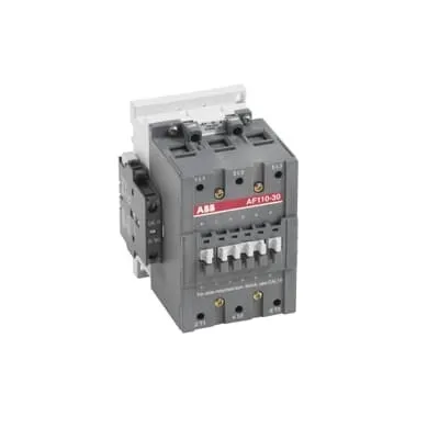
ABB 1SFL457010R9101 block contactor is a 3‑pole power switch designed for railway applications. Engineers often struggle with matching a wide coil voltage range to existing control circuits while keeping reliable operation in harsh environments. The device carries CE conformity, UL/CSA approvals, and other global certifications such as GL and RINA, supporting safety and regulatory compliance. With a 48–130 V control coil and a 1000 V main circuit rating, it fits rail automation, switchgear assemblies, and heavy‑duty control panels, reducing inventory and procurement complexity. Its compact 3P design and robust construction help minimize downtime in demanding environments.
Product Information
Extended Description
1SFL457010R9101 ABB: A 3-phase Contactor suitable for Rail way applications application. Operated with a wide voltage control voltage range 48-130 V, AC/DC
Minimum Order Quantity
1 piece
Customs Tariff Number
85364900
Replacement Product ID (NEW)
1SFL427002R1211
Data Sheet, Technical Information
1SBC100192C0206
Instructions and Manuals
Contactors A95, A110, UA95, UA110, AF95, AF110, AE95, AE110, TAE95, TAE110
Dimension Diagram
1SFB535001G1005
Product Net Width
102 mm
Product Net Depth / Length
123.5 mm
Product Net Height
148 mm
Product Net Weight
1.9 kg
Number of Main Contacts NO
3
Number of Main Contacts NC
0
Number of Auxiliary Contacts NO
0
Number of Auxiliary Contacts NC
0
Number of Poles
3P
Rated Operational Voltage
Main Circuit 1000 V
Rated Frequency (f)
Main Circuit 50 / 60 Hz
Conventional Free-air Thermal Current (Ith)
acc. to IEC 60947-4-1, Open Contactors Θ = 40 °C 160 A
Rated Operational Current AC-1 (Ie)
(690 V) 40 °C 160 A | (690 V) 55 °C 145 A | (690 V) 70 °C 130 A
Rated Operational Current AC-3 (Ie)
(415 V) 55 °C 110 A | (440 V) 55 °C 100 A | (500 V) 55 °C 100 A | (690 V) 55 °C 82 A | (1000 V) 55 °C 30 A | (380 / 400 V) 55 °C 110 A | (220 / 230 / 240 V) 55 °C 110
Rated Operational Current DC-1 (Ie)
(110 V) 2 Poles in Series, 40 °C 160 A | (220 V) 3 Poles in Series, 40 °C 160 A
Rated Operational Current DC-3 (Ie)
(110 V) 2 Poles in Series, 40 °C 160 A | (220 V) 3 Poles in Series, 40 °C 160 A
Rated Operational Current DC-5 (Ie)
(110 V) 2 Poles in Series, 40 °C 160 A | (220 V) 3 Poles in Series, 40 °C 160 A
Rated Operational Power AC-3 (Pe)
(415 V) 59 kW | (440 V) 59 kW | (500 V) 59 kW | (690 V) 75 kW | (1000 V) 40 kW | (380 / 400 V) 55 kW | (220 / 230 / 240 V) 30 kW
Rated Making Capacity AC-3
10 x Ie AC-3
Short-Circuit Protective Devices
gG Type Fuses 160 A
Maximum Breaking Capacity
cos phi=0.45 (cos phi=0.35 for Ie > 100 A) at 440 V 1160 A | cos phi=0.45 (cos phi=0.35 for Ie > 100 A) at 690 V 800 A
Rated Insulation Voltage (Ui)
acc. to IEC 60947-4-1 and VDE 0110 (Gr. C) 1000 V | acc. to UL/CSA 600 V
Rated Impulse Withstand Voltage (Uimp)
Main Circuit 8 kV
Maximum Electrical Switching Frequency
(AC-1) 300 cycles per hour | (AC-2 / AC-4) 150 cycles per hour | (AC-3) 300 cycles per hour
Mechanical Durability
10 million
Maximum Mechanical Switching Frequency
300 cycles per hour
Coil Operating Limits
(acc. to IEC 60947-4-1) 0.85 x Uc Min. ... 1.1 x Uc Max. (at θ ≤ 70 °C)
Rated Control Circuit Voltage (Uc)
50 Hz 48 ... 130 V | 60 Hz 48 ... 130 V | DC Operation 48 ... 130 V
Coil Consumption
Holding at Max. Rated Control Circuit Voltage 50 Hz 7 V·A | Holding at Max. Rated Control Circuit Voltage 60 Hz 7 V·A | Holding at Max. Rated Control Circuit Voltage DC 2 W | Pull-in at Max. Rated Control Circuit Voltage 50 Hz 350 V·A | Pull-in at Max. Rated Control Circuit Voltage 60 Hz 350 V·A | Pull-in at Max. Rated Control Circuit Voltage DC 400 W
Power Loss
at Rated Operating Conditions per Pole 3.5 W
Operate Time
Between Coil De-energization and NC Contact Closing 60 ... 130 ms | Between Coil De-energization and NO Contact Opening 55 ... 125 ms | Between Coil Energization and NC Contact Opening 27 ... 77 ms | Between Coil Energization and NO Contact Closing 30 ... 80 ms
Connecting Capacity Main Circuit
Bar 30 mm² | Flexible with Cable End 2 x 6 ... 35 mm² | Rigid 2 x 6 ... 65 mm²
Connecting Capacity Auxiliary Circuit
Flexible with Ferrule 2x 0.75 ... 2.5 mm² | Flexible with Insulated Ferrule 2x 0.75 ... 2.5 mm² | Flexible 2x0.75 ... 2.5 mm² | Solid 2 x 1 ... 4 mm² | Stranded 2 x 1 .... 4 mm²
Connecting Capacity
Bar 30 mm² | Flexible with Cable End 2 x 6 ... 35 mm² | Rigid 1 x 10 ... 95 mm²
Degree of Protection
acc. to IEC 60529, IEC 60947-1, EN 60529 Coil Terminals IP20 | acc. to IEC 60529, IEC 60947-1, EN 60529 Main Terminals IP10
Tightening Torque
Main Circuit 8 N·m
Terminal Type
Ring-Tongue Terminals
Product Name
Block Contactor
Maximum Operating Voltage UL/CSA
Main Circuit 600 V
General Use Rating UL/CSA
(600 V AC) 140 A
Horsepower Rating UL/CSA
(200 V AC) Three Phase 30 hp | (208 V AC) Three Phase 30 hp | (220 ... 240 V AC) Three Phase 40 hp | (440 ... 480 V AC) Three Phase 75 hp | (550 ... 600 V AC) Three Phase 100 hp
Full Load Amps Motor Use
(440 ... 480 V AC) Three Phase 96 A | (550 ... 600 V AC) Three Phase 99 A
Ambient Air Temperature
Close to Contactor Fitted with Thermal O/L Relay (0.85 ... 1.1 Uc) -25 ... 50 °C | Close to Contactor without Thermal O/L Relay (0.85 ... 1.1 Uc) -40 ... 70 °C | Close to Contactor for Storage -60 ... +80 °C
Maximum Operating Altitude Permissible
Without Derating 3000 m
Resistance to Shock acc. to IEC 60068-2-27
Half-sine Pulse for 11 ms, No Change in Contact Position, Open, Shock Direction: A 20 g | Half-sine Pulse for 11 ms, No Change in Contact Position, Closed, Shock Direction: A 20 g | Half-sine Pulse for 11 ms, No Change in Contact Position, Closed, Shock Direction: B1 15 g | Half-sine Pulse for 11 ms, No Change in Contact Position, Closed, Shock Direction: C1 20 g | Half-sine Pulse for 11 ms, No Change in Contact Position, Closed, Shock Direction: C2 20 g | Half-sine Pulse for 11 ms, No Change in Contact Position, Open, Shock Direction: B1 5 g | Half-sine Pulse for 11 ms, No Change in Contact Position, Open, Shock Direction: B2 15 g | Half-sine Pulse for 11 ms, No Change in Contact Position, Open, Shock Direction: C1 20 g | Half-sine Pulse for 11 ms, No Change in Contact Position, Open, Shock Direction: C2 20 g
RoHS Information
CE Declaration of Conformity - Contactor - A(F)95...A(F)300, AM110...AM300, UA95...UA110, (T)AE95....(T)AE110
RoHS Status
Following EU Directive 2011/65/EU
WEEE B2C / B2B
Business To Business
WEEE Category
5. Small Equipment (No External Dimension More Than 50 cm)
BV Certificate
13409/C0 BV
CB Certificate
SE-73663
CQC Certificate
CQC Certificate, Contactor, AF95, AF95...RT, AF95B...RT, AF110, AF110...RT, AF110B...RT, Made in Sweden
Declaration of Conformity - CCC
CCC Declaration of Conformity, Contactor, AF95, AF95...RT, AF95B...RT, AF110, AF110...RT, AF110B...RT, Made in Sweden
Declaration of Conformity - CE
CE Declaration of Conformity - Contactor - A(F)95...A(F)300, AM110...AM300, UA95...UA110, (T)AE95....(T)AE110
GL Certificate
GL_20260-04HH
LOVAG Certificate
SE9831016
LR Certificate
LR_04-00015-E1
RINA Certificate
ELE060313XG/002
RMRS Certificate
RMRS_12-03683-315
Package Level 1 Units
box 1 piece
Package Level 1 Width
130 mm
Package Level 1 Depth / Length
265 mm
Package Level 1 Height
162 mm
Package Level 1 Gross Weight
2.1 kg
Package Level 1 EAN
7320500256596
Object Classification Code
Q
ETIM 7
EC000066 - Power contactor, AC switching
ETIM 8
EC000066 - Power contactor, AC switching
ETIM 9
EC000066 - Power contactor, AC switching
eClass
V11.0 : 27371003
UNSPSC
39121529
IDEA Granular Category Code (IGCC)
4755 >> Contactors
Feature: Wide coil control voltage 48–130 V AC/DC reduces the need for multiple coil variants, lowering spare parts and stocking costs. Business impact: Simplifies procurement and streamlines control panel wiring across 50/60 Hz systems. Application: Ideal for rail vehicles and industrial drives where control voltage can vary. The product accommodates high power switching with reliable AC-3 operation, delivering predictable performance across temperatures and duty cycles. Feature: Rated main circuit voltage up to 1000 V and a 3‑pole, 3NO configuration. Business impact: Enables direct integration into high‑voltage actuator circuits and complex switchgear layouts, reducing component count. Application: Suitable for traction drives, signaling panels, and conveyor systems in rail and heavy industry. Feature: Mechanical durability of 10 million cycles and defined electrical life. Business impact: Extends maintenance intervals and lowers total cost of ownership. Application: Critical in safety‑critical control loops where uptime is essential. Feature: Flexible connecting capacity and robust terminations (30 mm² bus bars; 2×6–35 mm² flexible; 1×10–95 mm² rigid). Business impact: Simplifies installation, minimizes wiring errors, and speeds commissioning. Application: Ideal for panel builders and retrofit projects where wire routing is tight. Feature: Compliance and RoHS with multiple certifications (CE, UL/CSA, CCC, GL, RINA, LR). Business impact: Reduces regulatory risk and accelerates approvals in global markets. Application: Suitable for multinational projects and supplier‑consolidated sourcing.
Get a Quick Quote for a ABB 1SFL457010R9101
Chat with us on WhatsApp - fast responses guaranteed
Need to speak with someone? We'll call you back within 2 hours during business hours
Interested in ABB 1SFL457010R9101?
Enquire Now
FAQs
The device supports 30 mm² main circuit connections via bus bars, flexible leads rated 2 x 6–35 mm², and rigid 1 x 10–95 mm². Terminations use Ring-Tongue style connectors, and the unit offers IP40‑compatible interface points for reliable on‑site wiring while maintaining serviceability during maintenance.
Coil operating voltage ranges from 48 to 130 V for AC, DC operation, with 50/60 Hz compatibility. Main circuit ratings include up to 1000 V insulation and high‑current capability suitable for AC‑3 duty, depending on voltage and ambient temperature, ensuring appropriate performance across rail and industrial environments.
Yes, the contactor supports high‑voltage rail applications with Ie ratings specified for AC‑3 operation at 690 V and related voltages. Ie values vary by temperature and voltage (for example, up to around 110 A at 415–690 V and 55 °C), with protective margins at higher voltages to preserve switching reliability.
The product is CE marked and UL/CSA listed, with additional approvals such as CCC, GL, RINA, and LR. RoHS compliance is stated, and WEEE designation indicates proper end‑of‑life handling. These certifications support global regulatory compliance for industrial and railway electrical installations.
With a mechanical durability of 10 million cycles and low coil power consumption, maintenance intervals can be extended, reducing downtime. The wide coil range minimizes spare variants, lowering inventory costs, while high reliability under temperature and vibration enhances uptime, delivering a favorable ROI in rail and heavy‑duty automation projects.