ABB 1SFL457062R7211 Block Contactor - CE UL/CSA
Part Number: 1SFL457062R7211
Quick Summary
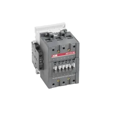
Block Contactor 1SFL457062R7211 by ABB is a 3-pole DC-controlled switch designed for railway and industrial drives. That capability helps you reliably manage high-current loads with a compact footprint. Many teams face coil voltage compatibility and installation challenges when upgrading legacy systems; this device streamlines integration with a wide 20–60 V DC control voltage range and ABB’s proven reliability. It carries essential certifications such as IEC 60947-4-1 and IEC 60947-1, along with UL/CSA and EN 50155 applicable parts, supporting global deployments in rail signaling, rolling stock, and heavy industry. By combining robust ratings with easy installation and standardization, it delivers reduced downtime and simplified spares management while enabling scalable control architectures for future-proof plants.
Product Information
Extended Description
1SFL457062R7211 ABB: A 3-phase Contactor suitable for Rail way applications application. Operated with a wide voltage control voltage range 20-60V, DC
Minimum Order Quantity
1 piece
Customs Tariff Number
85364900
Replacement Product ID (NEW)
1SFL427062R1122
Data Sheet, Technical Information
1SBC100192C0206
Instructions and Manuals
Contactors A95, A110, UA95, UA110, AF95, AF110, AE95, AE110, TAE95, TAE110
Dimension Diagram
1SFB535001G1005
Product Net Width
102 mm
Product Net Depth / Length
123.5 mm
Product Net Height
148 mm
Product Net Weight
1.9 kg
Number of Main Contacts NO
3
Number of Main Contacts NC
0
Number of Auxiliary Contacts NO
1
Number of Auxiliary Contacts NC
1
Number of Poles
3P
Standards
IEC/EN 60947-1, IEC/EN 60947-4-1, UL 60947-4-1, CSA C22.2 No. 60947-4-1, IEC 60077-1 (applicable parts), IEC 60077-2 (applicable parts), EN 50155 (applicable parts), TR CU 001/2011, IEC 61373, For compliance confirmation on applicable parts based on your application and combination, please consult your ABB sales representatives.
Rated Operational Voltage
Main Circuit 1000 V
Conventional Free-air Thermal Current (Ith)
acc. to IEC 60947-4-1, Open Contactors Θ = 40 °C 160 A
Rated Operational Current AC-1 (Ie)
(690 V) 40 °C 160 A | (690 V) 55 °C 145 A | (690 V) 70 °C 130 A
Rated Operational Current AC-3 (Ie)
(415 V) 55 °C 110 A | (440 V) 55 °C 100 A | (500 V) 55 °C 100 A | (690 V) 55 °C 82 A | (1000 V) 55 °C 30 A | (380 / 400 V) 55 °C 110 A | (220 / 230 / 240 V) 55 °C 110
Rated Operational Current DC-1 (Ie)
(110 V) 2 Poles in Series, 40 °C 160 A | (220 V) 3 Poles in Series, 40 °C 160 A
Rated Operational Current DC-3 (Ie)
(110 V) 2 Poles in Series, 40 °C 160 A | (220 V) 3 Poles in Series, 40 °C 160 A
Rated Operational Current DC-5 (Ie)
(110 V) 2 Poles in Series, 40 °C 160 A | (220 V) 3 Poles in Series, 40 °C 160 A
Rated Operational Power AC-3 (Pe)
(415 V) 59 kW | (440 V) 59 kW | (500 V) 59 kW | (690 V) 75 kW | (1000 V) 40 kW | (380 / 400 V) 55 kW | (220 / 230 / 240 V) 30 kW
Rated Breaking Capacity AC-3
8 x Ie AC-3
Rated Making Capacity AC-3
10 x Ie AC-3
Short-Circuit Protective Devices
gG Type Fuses 160 A
Maximum Breaking Capacity
cos phi=0.45 (cos phi=0.35 for Ie > 100 A) at 440 V 1160 A | cos phi=0.45 (cos phi=0.35 for Ie > 100 A) at 690 V 800 A
Rated Insulation Voltage (Ui)
acc. to IEC 60947-4-1 and VDE 0110 (Gr. C) 1000 V | acc. to UL/CSA 600 V
Rated Impulse Withstand Voltage (Uimp)
Main Circuit 8 kV
Maximum Electrical Switching Frequency
(AC-1) 300 cycles per hour | (AC-2 / AC-4) 150 cycles per hour | (AC-3) 300 cycles per hour
Mechanical Durability
10 million
Maximum Mechanical Switching Frequency
300 cycles per hour
Coil Operating Limits
(acc. to IEC 60947-4-1) 0.85 x Uc Min. ... 1.1 x Uc Max. (at θ ≤ 70 °C)
Rated Control Circuit Voltage (Uc)
DC Operation 20 ... 60 V
Coil Consumption
Holding at Max. Rated Control Circuit Voltage 50 Hz 7 V·A | Holding at Max. Rated Control Circuit Voltage 60 Hz 7 V·A | Holding at Max. Rated Control Circuit Voltage DC 2 W | Pull-in at Max. Rated Control Circuit Voltage 50 Hz 350 V·A | Pull-in at Max. Rated Control Circuit Voltage 60 Hz 350 V·A | Pull-in at Max. Rated Control Circuit Voltage DC 400 W
Power Loss
at Rated Operating Conditions per Pole 3.5 W
Operate Time
Between Coil De-energization and NC Contact Closing 60 ... 130 ms | Between Coil De-energization and NO Contact Opening 55 ... 125 ms | Between Coil Energization and NC Contact Opening 27 ... 77 ms | Between Coil Energization and NO Contact Closing 30 ... 80 ms
Connecting Capacity Main Circuit
Bar 30 mm² | Flexible with Cable End 2 x 6 ... 35 mm² | Rigid 2 x 6 ... 65 mm²
Connecting Capacity Auxiliary Circuit
Flexible with Ferrule 2x 0.75 ... 2.5 mm² | Flexible with Insulated Ferrule 2x 0.75 ... 2.5 mm² | Flexible 2x0.75 ... 2.5 mm² | Solid 2 x 1 ... 4 mm² | Stranded 2 x 1 .... 4 mm²
Connecting Capacity
Bar 30 mm² | Flexible with Cable End 2 x 6 ... 35 mm² | Rigid 2 x 6 ... 65 mm²
Degree of Protection
acc. to IEC 60529, IEC 60947-1, EN 60529 Coil Terminals IP20 | acc. to IEC 60529, IEC 60947-1, EN 60529 Main Terminals IP10
Connecting Terminals (delivered in open position) Main Poles
M8 hexagon socket screw with single connector
Tightening Torque
Main Circuit 8 N·m
Terminal Type
Ring-Tongue Terminals
Product Name
Block Contactor
Maximum Operating Voltage UL/CSA
Main Circuit 600 V
General Use Rating UL/CSA
(600 V AC) 140 A
Horsepower Rating UL/CSA
(200 V AC) Three Phase 30 hp | (208 V AC) Three Phase 30 hp | (220 ... 240 V AC) Three Phase 40 hp | (440 ... 480 V AC) Three Phase 75 hp | (550 ... 600 V AC) Three Phase 100 hp
Full Load Amps Motor Use
(440 ... 480 V AC) Three Phase 96 A | (550 ... 600 V AC) Three Phase 99 A
Ambient Air Temperature
Close to Contactor Fitted with Thermal O/L Relay (0.85 ... 1.1 Uc) -25 ... 50 °C | Close to Contactor without Thermal O/L Relay (0.85 ... 1.1 Uc) -40 ... 70 °C | Close to Contactor for Storage -60 ... +80 °C
Maximum Operating Altitude Permissible
Without Derating 3000 m
Resistance to Shock acc. to IEC 60068-2-27
Half-sine Pulse for 11 ms, No Change in Contact Position, Open, Shock Direction: A 20 g | Half-sine Pulse for 11 ms, No Change in Contact Position, Closed, Shock Direction: A 20 g | Half-sine Pulse for 11 ms, No Change in Contact Position, Closed, Shock Direction: B1 15 g | Half-sine Pulse for 11 ms, No Change in Contact Position, Closed, Shock Direction: C1 20 g | Half-sine Pulse for 11 ms, No Change in Contact Position, Closed, Shock Direction: C2 20 g | Half-sine Pulse for 11 ms, No Change in Contact Position, Open, Shock Direction: B1 5 g | Half-sine Pulse for 11 ms, No Change in Contact Position, Open, Shock Direction: B2 15 g | Half-sine Pulse for 11 ms, No Change in Contact Position, Open, Shock Direction: C1 20 g | Half-sine Pulse for 11 ms, No Change in Contact Position, Open, Shock Direction: C2 20 g
RoHS Information
CE Declaration of Conformity - Contactor - A(F)95...A(F)300, AM110...AM300, UA95...UA110, (T)AE95....(T)AE110
RoHS Status
Following EU Directive 2011/65/EU
WEEE B2C / B2B
Business To Business
WEEE Category
5. Small Equipment (No External Dimension More Than 50 cm)
ABS Certificate
ABS Certificate, Contactor, AF400...AF2050 (Sweden)
BV Certificate
13409/C0 BV
CB Certificate
SE-73665
CQC Certificate
CQC Certificate, Contactor, AF95, AF95...RT, AF95B...RT, AF110, AF110...RT, AF110B...RT, Made in Sweden
Declaration of Conformity - CCC
CCC Declaration of Conformity, Contactor, AF95, AF95...RT, AF95B...RT, AF110, AF110...RT, AF110B...RT, Made in Sweden
Declaration of Conformity - CE
CE Declaration of Conformity - Contactor - A(F)95...A(F)300, AM110...AM300, UA95...UA110, (T)AE95....(T)AE110
EAC Certificate
9AKK107046A8618
GL Certificate
GL_20260-04HH
LOVAG Certificate
SE-0145185
LR Certificate
LR_04-00015-E1
RINA Certificate
ELE060313XG/002
RMRS Certificate
RMRS_12-03683-315
Package Level 1 Units
box 1 piece
Package Level 1 Width
130 mm
Package Level 1 Depth / Length
265 mm
Package Level 1 Height
162 mm
Package Level 1 Gross Weight
2.1 kg
Package Level 1 EAN
7320500260234
Object Classification Code
Q
ETIM 7
EC000066 - Power contactor, AC switching
ETIM 8
EC000066 - Power contactor, AC switching
ETIM 9
EC000066 - Power contactor, AC switching
eClass
V11.0 : 27371003
UNSPSC
39121529
IDEA Granular Category Code (IGCC)
4755 >> Contactors
Feature: Wide control voltage range 20–60 V DC. Business Impact: Simplifies control logic and reduces wiring complexity by allowing common PLC outputs to operate the coil. Application: Railways and industrial drives with diverse control schemes. Feature: 3P main contacts with 1 NO/1 NC auxiliary contact. Business Impact: Enhanced monitoring and interlock options reduce misoperation and improve fault signaling. Application: Motor starter circuits and safety interlocks in conveyors and hoists. Feature: High insulation andVoltage rating up to 1000 V main circuit. Business Impact: Enables integration into higher-voltage systems without additional equipment or protection layers. Application: High-power switching in substations and rail traction electronics. Feature: AC-3 and DC-1/3/5 rated current capabilities. Business Impact: Supports a wide range of motor start/stop profiles, improving energy management and equipment utilization. Application: Conveyors, fans, pumps, and hoisting systems in heavy industry. Feature: Robust mechanical durability and protection levels. Business Impact: Reduces maintenance cycles and total cost of ownership with up to 10 million switching cycles. Application: Continuous-operation environments like manufacturing lines. Feature: Compact form factor with defined wiring and mounting interfaces. Business Impact: Easier retrofits and faster installation, minimizing site downtime. Application: Upgrades to existing control cabinets and railway equipment while preserving layout. Feature: Compliance with multiple certifications and standards. Business Impact: Frees engineering time on regulatory mapping and accelerates project approvals. Application: International deployments requiring CE, UL/CSA, and EN 50155 alignment.
Get a Quick Quote for a ABB 1SFL457062R7211
Chat with us on WhatsApp - fast responses guaranteed
Need to speak with someone? We'll call you back within 2 hours during business hours
Interested in ABB 1SFL457062R7211?
Enquire Now
FAQs
Install the 3P block contactor in a protected cabinet with proper clearance for the 102 mm width and 123.5 mm depth. Use the M8 terminal connections for main poles and ensure the coil terminals are wired to a 20–60 V DC control source. Confirm torque specifications at 8 N·m for mains connections and verify IP20 coil protection while ensuring ambient temperatures stay within -25 to 50 °C with the O/L relay fitted.
Yes, it supports high-voltage applications with main circuit insulation rated to 1000 V and AC-3 ratings including up to 110 A at 415 V or 110 A at 380–400 V, and 82 A at 690 V. The device also provides 30 A at 1000 V for specific DC- or resistive-load configurations, with short-circuit protection via compatible gG fuses.
The coil operates between 20 and 60 V DC, which aligns well with common PLC and automation controllers. Holding and pull-in currents are specified for 50 Hz and 60 Hz operation, enabling predictable coil behavior in control loops and reducing the risk of mis-coordination with other relay devices.
The ABB 1SFL457062R7211 carries CE Declarations of Conformity, UL/CSA listings, EN 50155 applicability, and IEC/UL/CSA standards compliance. This combination supports rail, transit, and industrial deployments by meeting safety, environmental, and performance requirements across multiple regions.
With a 10 million mechanical cycle rating and robust protection (IP20 coil, IP10 main terminals), maintenance intervals extend and spare parts usage reduces due to standardized ABB A95/AF110 style families. The coil’s wide voltage tolerance simplifies controls integration, lowering engineering time and downtime during commissioning and future upgrades.