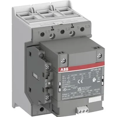
ABB AF146-30-11-32 Contactor - UL/CSA 1000 V rating
Part Number: 1SFL467001R3211
Quick Summary
AF146-30-11-32 Contactor is a 3-pole motor controller for up to 75 kW industrial drives. In unstable networks, wide control voltage tolerance minimizes nuisance trips and energy waste. Key certifications include CE, UL/CSA listings, and RoHS/REACH declarations to simplify global approvals. Designed for reliable installation in switchgear with add-on auxiliary blocks, this contactor supports energy-efficient automation and scalable control. Its AF technology tolerates large control voltage variations (48–130 V AC/DC), helping engineers design leaner panels. With a compact block-type design and built-in surge protection, it reduces wiring complexity and improves reliability. The device supports add-on auxiliary contacts for NO/NC configurations, enabling flexible control schemes.
Product Information
Extended Description
1SFL467001R3211 ABB: The AF146-30-11-32 is a 3 pole - 1000 V IEC or 600 V UL contactor with double clamp, controlling motors up to 75 kW / 400 V AC (AC-3) or 100 hp / 480 V UL and switching power circuits up to 225 A (AC-1) or 200 A UL general use. Thanks to the AF technology, the contactor has a wide control voltage range (48-130 V 50/60 Hz and DC), managing large control voltage variations, reducing panel energy consumptions and ensuring distinct operations in unstable networks. Furthermore, surge protection is built-in, offering a compact solution. AF contactors have a block type design, can be easily extended with add-on auxiliary contact blocks and an additional wide range of accessories.
Minimum Order Quantity
1 piece
Customs Tariff Number
8536490099
Data Sheet, Technical Information
1SBC100214C0202 - Main catalog Motor protection and control Manual motor starters, contactors and overload relays (PDF) - Edition 2024
Data Sheet, Technical Information (Part 2)
Contactors and Overload relays guide
Instructions and Manuals
Operating instruction, Contactor, AF(S)116, AF140, AF(S)146
CAD Dimensional Drawing
Information - 2D and 3D files for CAD systems
Product Net Width
90 mm
Product Net Depth / Length
138.5 mm
Product Net Height
150 mm
Product Net Weight
1.55 kg
Number of Main Contacts NO
3
Number of Main Contacts NC
0
Number of Auxiliary Contacts NO
1
Number of Auxiliary Contacts NC
1
Number of Poles
3P
Rated Operational Voltage
Main Circuit 1000 V
Rated Frequency (f)
Main Circuit 50 / 60 Hz
Conventional Free-air Thermal Current (Ith)
acc. to IEC 60947-4-1, Open Contactors Θ = 40 °C 225 A
Rated Operational Current AC-1 (Ie)
(1000 V) 40 °C 225 A | (1000 V) 60 °C 200 A | (1000 V) 70 °C 175 A | (690 V) 40 °C 225 A | (690 V) 60 °C 200 A | (690 V) 70 °C 175 A
Rated Operational Current AC-3 (Ie)
(415 V) 60 °C 146 A | (440 V) 60 °C 146 A | (500 V) 60 °C 130 A | (690 V) 60 °C 93 A | (1000 V) 60 °C 60 A | (380 / 400 V) 60 °C 146 A | (220 / 230 / 240 V) 60 °C 146 A
Rated Operational Current AC-3e (Ie)
(415 V) 60 °C 146 A | (440 V) 60 °C 146 A | (500 V) 60 °C 130 A | (690 V) 60 °C 93 A | (1000 V) 60 °C 54 A | (380 / 400 V) 60 °C 146 A | (220 / 230 / 240 V) 60 °C 146 A
Rated Operational Power AC-3 (Pe)
(415 V) 75 kW | (440 V) 90 kW | (500 V) 90 kW | (690 V) 90 kW | (380 / 400 V) 75 kW | (220 / 230 / 240 V) 45 kW
Rated Operational Power AC-3e (Pe)
(415 V) 75 kW | (440 V) 90 kW | (500 V) 90 kW | (690 V) 90 kW | (1000 V) 75 kW | (380 / 400 V) 75 kW | (220 / 230 / 240 V) 45 kW
Rated Breaking Capacity AC-3
8 x Ie AC-3
Rated Breaking Capacity AC-3e
8.5 x Ie AC-3e
Rated Making Capacity AC-3
10 x Ie AC-3
Rated Making Capacity AC-3e
12 x Ie AC-3e
Rated Short-time Withstand Current Low Voltage (Icw)
at 40 °C Ambient Temp, in Free Air, from a Cold State 10 s 1168 A | at 40 °C Ambient Temp, in Free Air, from a Cold State 15 min 225 A | at 40 °C Ambient Temp, in Free Air, from a Cold State 1 min 477 A | at 40 °C Ambient Temp, in Free Air, from a Cold State 1 s 1460 A | at 40 °C Ambient Temp, in Free Air, from a Cold State 30 s 674 A
Maximum Breaking Capacity
cos phi=0.45 (cos phi=0.35 for Ie > 100 A) at 440 V 3000 A | cos phi=0.45 (cos phi=0.35 for Ie > 100 A) at 690 V 1500 A
Rated Insulation Voltage (Ui)
acc. to IEC 60947-4-1 and VDE 0110 (Gr. C) 1000 V | acc. to UL/CSA 1000 V
Rated Impulse Withstand Voltage (Uimp)
Main Circuit 8 kV
Maximum Electrical Switching Frequency
(AC-1) 300 cycles per hour | (AC-2 / AC-4) 150 cycles per hour | (AC-3) 300 cycles per hour
Mechanical Durability
5 million
Maximum Mechanical Switching Frequency
300 cycles per hour
Rated Control Circuit Voltage (Uc)
50 Hz 48 ... 130 V | 60 Hz 48 ... 130 V | DC Operation 48 ... 130 V
Coil Consumption
Holding at Max. Rated Control Circuit Voltage 50 Hz 6 V·A | Holding at Max. Rated Control Circuit Voltage 50 Hz 2 W | Holding at Max. Rated Control Circuit Voltage 60 Hz 6 V·A | Holding at Max. Rated Control Circuit Voltage 60 Hz 2 W | Holding at Max. Rated Control Circuit Voltage DC 2.5 W | Pull-in at Max. Rated Control Circuit Voltage 50 Hz 180 V·A | Pull-in at Max. Rated Control Circuit Voltage 60 Hz 180 V·A | Pull-in at Max. Rated Control Circuit Voltage DC 150 W
Power Loss
at Rated Operating Conditions AC-1 per Pole 23 W | at Rated Operating Conditions AC-3 per Pole 10 W
Operate Time
Between Coil De-energization and NO Contact Opening 40 ... 70 ms | Between Coil Energization and NO Contact Closing 20 ... 55 ms
Connecting Capacity Main Circuit
Flexible 2 x 10 ... 70 mm² | Rigid Cu-Cable 1 x 10 ... 95 mm²
Connecting Capacity Auxiliary Circuit
Flexible with Ferrule 1x 0.75 ... 2.5 mm² | Flexible with Ferrule 2x 0.75 ... 2.5 mm² | Flexible with Insulated Ferrule 1x 0.75 ... 2.5 mm² | Flexible with Insulated Ferrule 2x 0.75 ... 2.5 mm² | Flexible 1x 0.75 ... 2.5 mm² | Flexible 2x 0.75 ... 2.5 mm² | Solid 1x 1 ... 4 mm² | Solid 2x 1 ... 4 mm² | Stranded 1x 1 ... 4 mm² | Stranded 2x 1 ... 4 mm²
Connecting Capacity
Flexible 1 x 10 ... 70 mm² | Flexible 2 x 10 ... 70 mm² | Rigid Cu-Cable 1 x 10 ... 95 mm²
Wire Stripping Length
Auxiliary Circuit 9 mm | Control Circuit 9 mm
Degree of Protection
acc. to IEC 60529, IEC 60947-1, EN 60529 Coil Terminals IP20 | acc. to IEC 60529, IEC 60947-1, EN 60529 Main Terminals IP00
Recommended Screw Driver
Main Circuit M6 | Control Circuit M3.5
Tightening Torque
Auxiliary Circuit 1 N·m | Cable Lug 9 N·m | Control Circuit 1 N·m | Main Circuit 8 N·m
Terminal Type
Double Clamp
Product Name
Block Contactor
Maximum Operating Voltage UL/CSA
Main Circuit 1000 V
General Use Rating UL/CSA
(1000 V AC) 200 A
Horsepower Rating UL/CSA
(200 ... 208 V AC) Three Phase 40 hp | (220 ... 240 V AC) Three Phase 50 hp | (440 ... 480 V AC) Three Phase 100 hp | (550 ... 600 V AC) Three Phase 125 hp
Tightening Torque UL/CSA
Auxiliary Circuit 9 in·lb | Control Circuit 9 in·lb | Main Circuit 71 in·lb
Full Load Amps Motor Use
(200 ... 208 V AC) Three Phase 120 A | (220 ... 240 V AC) Three Phase 130 A | (440 ... 480 V AC) Three Phase 124 A | (550 ... 600 V AC) Three Phase 125 A
Ambient Air Temperature
Close to Contactor Fitted with Thermal O/L Relay (0.85 ... 1.1 Uc) -25 ... 55 °C | Close to Contactor without Thermal O/L Relay (0.85 ... 1.1 Uc) -40 ... 70 °C | Close to Contactor for Storage -40 ... 70 °C
Maximum Operating Altitude Permissible
Without Derating 3000 m
Conflict Minerals Reporting Template (CMRT)
CMRT - Conflict Minerals Reporting Template
REACH Declaration
REACH - Letter of Confirmation for block contactors, contactor relays, installation contactors, mini contactors, mini contactor relays, thermal overload relays, electronic overload relays and related accessories
RoHS Information
RoHS II declaration for block contactors, installation contactors, mini contactors, mini contactor relays, thermal overload relays, electronic overload relays and related accessories
RoHS Status
Following EU Directive 2011/65/EU and Amendment 2015/863 July 22, 2019
Toxic Substances Control Act - TSCA
Toxic Substances Control Act (TSCA) declaration for Contactors
WEEE B2C / B2B
Business To Business
WEEE Category
5. Small Equipment (No External Dimension More Than 50 cm)
End Of Life Disassembling Instructions
End-of-life instruction - AF(S)116(B)-**(RT) to AF(S)205(B)-**(RT)
A2L Certificate – UL
UL Certificate of Compliance A2L, Contactor, AF116 - AF146
Declaration of Conformity - CE
CE Declaration of Conformity - Contactor - AF116...AF370
Declaration of Conformity - UKCA
UK Declaration of Conformity - Contactors >100A
UL Certificate
cULus Certificate, Contactor, AF116-30...AF146-30, AFS116-30...AFS146-30
Package Level 1 Units
box 1 piece
Package Level 1 Width
207 mm
Package Level 1 Depth / Length
216 mm
Package Level 1 Height
150 mm
Package Level 1 Gross Weight
1.75 kg
Package Level 1 EAN
7320500560488
Object Classification Code
Q
ETIM 7
EC000066 - Power contactor, AC switching
ETIM 8
EC000066 - Power contactor, AC switching
ETIM 9
EC000066 - Power contactor, AC switching
eClass
V11.0 : 27371003
UNSPSC
39121529
IDEA Granular Category Code (IGCC)
4758 >> Iec Contactors
The AF146-30-11-32 uses AF technology to manage wide control voltage variations, which translates to reduced energy consumption and fewer nuisance trips in panel power supplies, improving overall system reliability and reducing maintenance costs. This is particularly valuable in environments with fluctuating supply voltages or unstable networks, enabling consistent motor control without frequent reconfigurations. Its 3P main circuit is rated up to 1000 V, supporting high-power motor starts and providing a robust solution for IEC/UL motor control in industrial applications, such as conveyors, pumps, and machine tools. The built-in surge protection and block-type design simplify panel wiring and maintenance, accelerating commissioning and future upgrades while preserving space. Compatibility with auxiliary contact blocks offers scalable NO/NC configurations to support diverse control schemes without replacing the base unit. The contactor’s IP20 coil terminals and IP00 main terminals, along with double clamp connections, deliver secure, vibration-tolerant terminations for demanding factory floors. Customer teams benefit from predictable switching performance, high mechanical durability (up to 5 million cycles), and long-term cost reduction through fewer part replacements. By meeting RoHS, REACH, and UL/CSA declarations, this device supports compliance-driven projects and global deployments. Engineers appreciate the clear data on current ratings: Ie up to 225 A (AC-1 at 1000 V, 40 °C) and up to 146 A (AC-3 at 415–690 V), enabling accurate motor sizing and protective coordination. The low coil power during holding and pull-in periods helps limit panel heat gain, contributing to overall energy efficiency and cooler switchgear enclosures. With 90 mm width, 138.5 mm depth, and 150 mm height, plus a 1.55 kg weight, installation fits within standard DIN rail or fixed panel configurations. The unit supports flexible conductor connections (2 x 10–70 mm² for main circuit) and 1 x 1–4 mm² auxiliary conductors, simplifying field wiring and reducing installation time. These features collectively deliver a reliable, scalable solution for modern automation projects while addressing common objections about high-power contactors in compact control panels.
Get a Quick Quote for a ABB 1SFL467001R3211
Chat with us on WhatsApp - fast responses guaranteed
Need to speak with someone? We'll call you back within 2 hours during business hours
Interested in ABB 1SFL467001R3211?
Enquire Now
FAQs
Plan for three main-conductor connections using flexible 2 x 10 to 70 mm² or rigid 1 x 10 to 95 mm² for the main circuit, and 1 x 0.75 to 2.5 mm² or 2 x 0.75 to 2.5 mm² for the auxiliary circuit. Utilize the double clamp terminals for secure, vibration-resistant terminations and respect the IP ratings: IP20 on coil terminals and IP00 on main terminals. Allow space for potential add-on auxiliary blocks to enable NO/NC configurations as your system evolves.
Main circuit rated voltage is up to 1000 V with a 50/60 Hz rating. Rated operational current AC-1 is up to 225 A at 1000 V (40 °C) and 200 A at 1000 V (60 °C). For AC-3, Ie reaches 146 A at 415–690 V (various temperatures). The unit delivers up to 75 kW AC-3 at 415 V and 90 kW at higher voltages, with corresponding HP ratings on UL/CSA documentation.
Yes. The AF146-30-11-32 is CE compliant with a CE Declaration of Conformity and UL/CSA listed for main circuit operation up to 1000 V. It also carries RoHS and REACH declarations to support global manufacturing and regulatory requirements, along with UKCA where applicable. This makes it suitable for multinational facilities and cross-border supply chains.
The AF146-30-11-32 is designed for extension with auxiliary contact blocks, enabling NO/NC configurations to accommodate varied control logic without replacing the base device. This preserves panel space, simplifies wiring, and supports scalable control architectures. Extended auxiliary contacts maintain the same mechanical durability and electrical ratings while expanding signaling options for interlocks, feedback loops, and remote control.
Expect a mechanical durability rating of up to 5 million switching cycles under typical industrial use, with a maximum switching frequency of 300 cycles per hour for AC-3 and AC-1. Regular inspection of terminal connections, coil voltage verification within the 48–130 V range, and adherence to tightening torques (Main Circuit 71 in-lb, Auxiliary 9 in-lb, Control 9 in-lb) will help sustain reliability. Built-in surge protection and compact design reduce field servicing and downtime.