ABB AF146-30-22-32 Contactor - 1000 V UL/CE certified
Part Number: 1SFL467001R3222
Quick Summary
The ABB AF146-30-22-32 Contactor enables reliable three-pole motor control for industrial applications. Fluctuating control voltages and unstable networks can cause nuisance tripping and energy losses. It meets CE and UKCA conformity, UL/CSA listings for general use, and RoHS/REACH compliance. Powered by AF technology, it tolerates wide coil voltage variation, reducing panel energy use and preventing unexpected stops. Its compact block design with surge protection and extendable auxiliary contacts simplifies installation and ongoing maintenance. Designed for AC-1 and AC-3 loads up to 75 kW at 400 V, it supports flexible wiring and quick CAD integration for panel builders. This makes it a cost-effective choice for OEMs seeking reliable starting protection across varied supply conditions.
Product Information
Extended Description
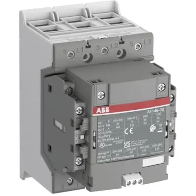
1SFL467001R3222 ABB: The AF146-30-22-32 is a 3 pole - 1000 V IEC or 600 V UL contactor with double clamp, controlling motors up to 75 kW / 400 V AC (AC-3) or 100 hp / 480 V UL and switching power circuits up to 225 A (AC-1) or 200 A UL general use. Thanks to the AF technology, the contactor has a wide control voltage range (48-130 V 50/60 Hz and DC), managing large control voltage variations, reducing panel energy consumptions and ensuring distinct operations in unstable networks. Furthermore, surge protection is built-in, offering a compact solution. AF contactors have a block type design, can be easily extended with add-on auxiliary contact blocks and an additional wide range of accessories.
Minimum Order Quantity
1 piece
Customs Tariff Number
8536490099
Data Sheet, Technical Information
1SBC100214C0202 - Main catalog Motor protection and control Manual motor starters, contactors and overload relays (PDF) - Edition 2024
Data Sheet, Technical Information (Part 2)
Contactors and Overload relays guide
Instructions and Manuals
Operating instruction, Contactor, AF(S)116, AF140, AF(S)146
CAD Dimensional Drawing
Information - 2D and 3D files for CAD systems
Product Net Width
110 mm
Product Net Depth / Length
138.5 mm
Product Net Height
150 mm
Product Net Weight
1.55 kg
Number of Main Contacts NO
3
Number of Main Contacts NC
0
Number of Auxiliary Contacts NO
2
Number of Auxiliary Contacts NC
2
Number of Poles
3P
Rated Operational Voltage
Main Circuit 1000 V
Rated Frequency (f)
Main Circuit 50 / 60 Hz
Conventional Free-air Thermal Current (Ith)
acc. to IEC 60947-4-1, Open Contactors Θ = 40 °C 225 A
Rated Operational Current AC-1 (Ie)
(1000 V) 40 °C 225 A | (1000 V) 60 °C 200 A | (1000 V) 70 °C 175 A | (690 V) 40 °C 225 A | (690 V) 60 °C 200 A | (690 V) 70 °C 175 A
Rated Operational Current AC-3 (Ie)
(415 V) 60 °C 146 A | (440 V) 60 °C 146 A | (500 V) 60 °C 130 A | (690 V) 60 °C 93 A | (1000 V) 60 °C 60 A | (380 / 400 V) 60 °C 146 A | (220 / 230 / 240 V) 60 °C 146 A
Rated Operational Current AC-3e (Ie)
(415 V) 60 °C 146 A | (440 V) 60 °C 146 A | (500 V) 60 °C 130 A | (690 V) 60 °C 93 A | (1000 V) 60 °C 54 A | (380 / 400 V) 60 °C 146 A | (220 / 230 / 240 V) 60 °C 146 A
Rated Operational Power AC-3 (Pe)
(415 V) 75 kW | (440 V) 90 kW | (500 V) 90 kW | (690 V) 90 kW | (380 / 400 V) 75 kW | (220 / 230 / 240 V) 45 kW
Rated Operational Power AC-3e (Pe)
(415 V) 75 kW | (440 V) 90 kW | (500 V) 90 kW | (690 V) 90 kW | (1000 V) 75 kW | (380 / 400 V) 75 kW | (220 / 230 / 240 V) 45 kW
Rated Breaking Capacity AC-3
8 x Ie AC-3
Rated Breaking Capacity AC-3e
8.5 x Ie AC-3e
Rated Making Capacity AC-3
10 x Ie AC-3
Rated Making Capacity AC-3e
12 x Ie AC-3e
Rated Short-time Withstand Current Low Voltage (Icw)
at 40 °C Ambient Temp, in Free Air, from a Cold State 10 s 1168 A | at 40 °C Ambient Temp, in Free Air, from a Cold State 15 min 225 A | at 40 °C Ambient Temp, in Free Air, from a Cold State 1 min 477 A | at 40 °C Ambient Temp, in Free Air, from a Cold State 1 s 1460 A | at 40 °C Ambient Temp, in Free Air, from a Cold State 30 s 674 A
Maximum Breaking Capacity
cos phi=0.45 (cos phi=0.35 for Ie > 100 A) at 440 V 3000 A | cos phi=0.45 (cos phi=0.35 for Ie > 100 A) at 690 V 1500 A
Rated Insulation Voltage (Ui)
acc. to IEC 60947-4-1 and VDE 0110 (Gr. C) 1000 V | acc. to UL/CSA 1000 V
Rated Impulse Withstand Voltage (Uimp)
Main Circuit 8 kV
Maximum Electrical Switching Frequency
(AC-1) 300 cycles per hour | (AC-2 / AC-4) 150 cycles per hour | (AC-3) 300 cycles per hour
Mechanical Durability
5 million
Maximum Mechanical Switching Frequency
300 cycles per hour
Rated Control Circuit Voltage (Uc)
50 Hz 48 ... 130 V | 60 Hz 48 ... 130 V | DC Operation 48 ... 130 V
Coil Consumption
Holding at Max. Rated Control Circuit Voltage 50 Hz 6 V·A | Holding at Max. Rated Control Circuit Voltage 50 Hz 2 W | Holding at Max. Rated Control Circuit Voltage 60 Hz 6 V·A | Holding at Max. Rated Control Circuit Voltage 60 Hz 2 W | Holding at Max. Rated Control Circuit Voltage DC 2.5 W | Pull-in at Max. Rated Control Circuit Voltage 50 Hz 180 V·A | Pull-in at Max. Rated Control Circuit Voltage 60 Hz 180 V·A | Pull-in at Max. Rated Control Circuit Voltage DC 150 W
Power Loss
at Rated Operating Conditions AC-1 per Pole 23 W | at Rated Operating Conditions AC-3 per Pole 10 W
Operate Time
Between Coil De-energization and NO Contact Opening 40 ... 70 ms | Between Coil Energization and NO Contact Closing 20 ... 55 ms
Connecting Capacity Main Circuit
Flexible 2 x 10 ... 70 mm² | Rigid Cu-Cable 1 x 10 ... 95 mm²
Connecting Capacity Auxiliary Circuit
Flexible with Ferrule 1x 0.75 ... 2.5 mm² | Flexible with Ferrule 2x 0.75 ... 2.5 mm² | Flexible with Insulated Ferrule 1x 0.75 ... 2.5 mm² | Flexible with Insulated Ferrule 2x 0.75 ... 2.5 mm² | Flexible 1x 0.75 ... 2.5 mm² | Flexible 2x 0.75 ... 2.5 mm² | Solid 1x 1 ... 4 mm² | Solid 2x 1 ... 4 mm² | Stranded 1x 1 ... 4 mm² | Stranded 2x 1 ... 4 mm²
Connecting Capacity
Flexible 1 x 10 ... 70 mm² | Flexible 2 x 10 ... 70 mm² | Rigid Cu-Cable 1 x 10 ... 95 mm²
Wire Stripping Length
Auxiliary Circuit 9 mm | Control Circuit 9 mm
Degree of Protection
acc. to IEC 60529, IEC 60947-1, EN 60529 Coil Terminals IP20 | acc. to IEC 60529, IEC 60947-1, EN 60529 Main Terminals IP00
Recommended Screw Driver
Main Circuit M6 | Control Circuit M3.5
Tightening Torque
Auxiliary Circuit 1 N·m | Cable Lug 9 N·m | Control Circuit 1 N·m | Main Circuit 8 N·m
Terminal Type
Double Clamp
Product Name
Block Contactor
Maximum Operating Voltage UL/CSA
Main Circuit 1000 V
General Use Rating UL/CSA
(1000 V AC) 200 A
Horsepower Rating UL/CSA
(200 ... 208 V AC) Three Phase 40 hp | (220 ... 240 V AC) Three Phase 50 hp | (440 ... 480 V AC) Three Phase 100 hp | (550 ... 600 V AC) Three Phase 125 hp
Tightening Torque UL/CSA
Auxiliary Circuit 9 in·lb | Control Circuit 9 in·lb | Main Circuit 71 in·lb
Full Load Amps Motor Use
(200 ... 208 V AC) Three Phase 120 A | (220 ... 240 V AC) Three Phase 130 A | (440 ... 480 V AC) Three Phase 124 A | (550 ... 600 V AC) Three Phase 125 A
Ambient Air Temperature
Close to Contactor Fitted with Thermal O/L Relay (0.85 ... 1.1 Uc) -25 ... 55 °C | Close to Contactor without Thermal O/L Relay (0.85 ... 1.1 Uc) -40 ... 70 °C | Close to Contactor for Storage -40 ... 70 °C
Maximum Operating Altitude Permissible
Without Derating 3000 m
Conflict Minerals Reporting Template (CMRT)
CMRT - Conflict Minerals Reporting Template
REACH Declaration
REACH - Letter of Confirmation for block contactors, contactor relays, installation contactors, mini contactors, mini contactor relays, thermal overload relays, electronic overload relays and related accessories
RoHS Information
RoHS II declaration for block contactors, installation contactors, mini contactors, mini contactor relays, thermal overload relays, electronic overload relays and related accessories
RoHS Status
Following EU Directive 2011/65/EU and Amendment 2015/863 July 22, 2019
Toxic Substances Control Act - TSCA
Toxic Substances Control Act (TSCA) declaration for Contactors
WEEE B2C / B2B
Business To Business
WEEE Category
5. Small Equipment (No External Dimension More Than 50 cm)
End Of Life Disassembling Instructions
End-of-life instruction - AF(S)116(B)-**(RT) to AF(S)205(B)-**(RT)
A2L Certificate – UL
UL Certificate of Compliance A2L, Contactor, AF116 - AF146
Declaration of Conformity - CE
CE Declaration of Conformity - Contactor - AF116...AF370
Declaration of Conformity - UKCA
UK Declaration of Conformity - Contactors >100A
UL Certificate
cULus Certificate, Contactor, AF116-30...AF146-30, AFS116-30...AFS146-30
Package Level 1 Units
box 1 piece
Package Level 1 Width
207 mm
Package Level 1 Depth / Length
216 mm
Package Level 1 Height
150 mm
Package Level 1 Gross Weight
1.75 kg
Package Level 1 EAN
7320500560495
Object Classification Code
Q
ETIM 7
EC000066 - Power contactor, AC switching
ETIM 8
EC000066 - Power contactor, AC switching
ETIM 9
EC000066 - Power contactor, AC switching
eClass
V11.0 : 27371003
UNSPSC
39121529
IDEA Granular Category Code (IGCC)
4758 >> Iec Contactors
Feature AF technology provides a wide control voltage range of 48-130 V AC/DC, allowing operation under fluctuating supply without tripping. Business Impact This reduces energy waste and improves reliability in unstable networks. Application Suitable for manufacturing lines with variable power quality. Feature Built-in surge protection reduces risk of contact and downstream electronics damage, lowering panel downtime and maintenance costs. Application Ideal for conveyors, pumps, and heavy-load switching in demanding environments. Feature Block-type design plus extendable auxiliary contact blocks enables scalable control logic and flexible retrofits. Application Great for OEM panels that evolve with process changes and expansion. Feature Rated currents AC-1 up to 225 A and AC-3 up to 146 A at multiple voltages, with 75 kW at 415/440/380 V AC-3 capability. Application Supports high-demand motor start-ups in packaging, water treatment, and material handling. Feature Coil consumption and power loss data provide clear guidance for panel energy budgeting: Holding around 2 W; Pull-in 180 V·A; 23 W per pole (AC-1) and 10 W per pole (AC-3). Application Enables accurate thermal management and panel design. Feature Flexible main-circuit connections (2 x 10-70 mm²) plus rigid Cu-cable options (1 x 10-95 mm²) with standard Double Clamp terminals. Torque specs by terminal ensure reliable, vibration-resistant wiring. Application Suited for compact control panels in harsh environments. Feature Environmental rating and durability: IP20 coil terminals, IP00 main terminals, ambient -25 to 55°C, up to 3000 m altitude, and 5 million mechanical cycles. Application Robust motor protection in automotive, process, and heavy industry. Feature Compliance: CE, UKCA, UL/CSA, RoHS, REACH, and WEEE B2B alignment with end-of-life documentation. Application Global manufacturing and OEM supply chains demand proven standards compliance.
Get a Quick Quote for a ABB 1SFL467001R3222
Chat with us on WhatsApp - fast responses guaranteed
Need to speak with someone? We'll call you back within 2 hours during business hours
Interested in ABB 1SFL467001R3222?
Enquire Now
FAQs
The AF146-30-22-32 uses a block contactor design with Double Clamp terminals for secure connections. Main circuit connections support Flexible 2 x 10-70 mm² or rigid Cu-Cable 1 x 10-95 mm², complemented by optional auxiliary blocks. This combination simplifies wiring in compact panels and reduces rework time during installation.
For AC-1 operation at 1000 V, the contactor achieves up to 225 A (40 °C) and 200 A (60 °C), down to 175 A (70 °C). For AC-3 at 415–690 V, ratings are 146 A (60 °C) across several voltages, with AC-3e ratings up to 146 A and per‑pole power up to 75 kW at 380–400 V. These figures translate to robust motor-starting performance.
Yes. The AF146-30-22-32 incorporates AF technology with a wide control voltage range of 48–130 V (AC) or DC, tolerating voltage variations. It also features built-in surge protection, reducing damage risk and extending component life in networks with spikes and fluctuations, which reduces downtime and maintenance costs for critical equipment.
The device is CE and UKCA compliant, UL/CSA listed for general use, and RoHS and REACH compliant. WEEE B2B classification applies, and ABB provides end-of-life disassembly instructions, supporting global regulatory compliance and responsible sustainability programs.
Expect improved reliability from wide-voltage tolerance and surge protection, reducing nuisance trips. Mechanical durability of 5 million cycles and low coil power (2 W hold, 180 VA pull-in) lower energy use and maintenance intervals. The extendable auxiliary contacts and compact design also reduce panel footprint and installation costs.