ABB AF146-30-22B-31 Block Contactor - 1000 V IEC/UL
Part Number: 1SFL467002R3122
Quick Summary
ABB AF146-30-22B-31 Block Contactor is a 3-pole switch for motor control up to 75 kW at 400 V AC. In busy panels, voltage fluctuations and inconsistent coil voltages can cause failed starts and energy waste; this device mitigates that with AF technology that tolerates wide control voltage variations. Certified to CE and UL/CSA standards, with UKCA registration and RoHS/REACH declarations, it also offers built-in surge protection for robust operation. By enabling easy expansion with auxiliary contact blocks, it supports scalable control circuits and simplified wiring, delivering reliable performance and lower total cost of ownership in automated machinery and process lines.
Product Information
Extended Description
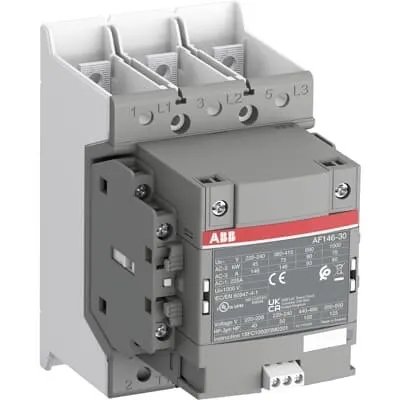
1SFL467002R3122 ABB: The AF146-30-22B-31 is a 3 pole - 1000 V IEC or 600 V UL contactor with Main Circuit Bars, controlling motors up to 75 kW / 400 V AC (AC-3) or 100 hp / 480 V UL and switching power circuits up to 225 A (AC-1) or 200 A UL general use. Thanks to the AF technology, the contactor has a wide control voltage range (24-60 V 50/60 Hz and 20-60 V DC), managing large control voltage variations, reducing panel energy consumptions and ensuring distinct operations in unstable networks. Furthermore, surge protection is built-in, offering a compact solution. AF contactors have a block type design, can be easily extended with add-on auxiliary contact blocks and an additional wide range of accessories.
Minimum Order Quantity
1 piece
Customs Tariff Number
8536490099
Data Sheet, Technical Information
1SBC100214C0202 - Main catalog Motor protection and control Manual motor starters, contactors and overload relays (PDF) - Edition 2024
Data Sheet, Technical Information (Part 2)
Contactors and Overload relays guide
Instructions and Manuals
Operating instruction, Contactor, AF(S)116, AF140, AF(S)146
CAD Dimensional Drawing
Information - 2D and 3D files for CAD systems
Product Net Width
110 mm
Product Net Depth / Length
138.5 mm
Product Net Height
150 mm
Product Net Weight
1.3 kg
Number of Main Contacts NO
3
Number of Main Contacts NC
0
Number of Auxiliary Contacts NO
2
Number of Auxiliary Contacts NC
2
Number of Poles
3P
Rated Operational Voltage
Main Circuit 1000 V
Rated Frequency (f)
Main Circuit 50 / 60 Hz
Conventional Free-air Thermal Current (Ith)
acc. to IEC 60947-4-1, Open Contactors Θ = 40 °C 225 A
Rated Operational Current AC-1 (Ie)
(1000 V) 40 °C 225 A | (1000 V) 60 °C 200 A | (1000 V) 70 °C 175 A | (690 V) 40 °C 225 A | (690 V) 60 °C 200 A | (690 V) 70 °C 175 A
Rated Operational Current AC-3 (Ie)
(415 V) 60 °C 146 A | (440 V) 60 °C 146 A | (500 V) 60 °C 130 A | (690 V) 60 °C 93 A | (1000 V) 60 °C 60 A | (380 / 400 V) 60 °C 146 A | (220 / 230 / 240 V) 60 °C 146 A
Rated Operational Current AC-3e (Ie)
(415 V) 60 °C 146 A | (440 V) 60 °C 146 A | (500 V) 60 °C 130 A | (690 V) 60 °C 93 A | (1000 V) 60 °C 54 A | (380 / 400 V) 60 °C 146 A | (220 / 230 / 240 V) 60 °C 146 A
Rated Operational Power AC-3 (Pe)
(415 V) 75 kW | (440 V) 90 kW | (500 V) 90 kW | (690 V) 90 kW | (380 / 400 V) 75 kW | (220 / 230 / 240 V) 45 kW
Rated Operational Power AC-3e (Pe)
(415 V) 75 kW | (440 V) 90 kW | (500 V) 90 kW | (690 V) 90 kW | (1000 V) 75 kW | (380 / 400 V) 75 kW | (220 / 230 / 240 V) 45 kW
Rated Breaking Capacity AC-3
8 x Ie AC-3
Rated Breaking Capacity AC-3e
8.5 x Ie AC-3e
Rated Making Capacity AC-3
10 x Ie AC-3
Rated Making Capacity AC-3e
12 x Ie AC-3e
Rated Short-time Withstand Current Low Voltage (Icw)
at 40 °C Ambient Temp, in Free Air, from a Cold State 10 s 1168 A | at 40 °C Ambient Temp, in Free Air, from a Cold State 15 min 225 A | at 40 °C Ambient Temp, in Free Air, from a Cold State 1 min 477 A | at 40 °C Ambient Temp, in Free Air, from a Cold State 1 s 1460 A | at 40 °C Ambient Temp, in Free Air, from a Cold State 30 s 674 A
Maximum Breaking Capacity
cos phi=0.45 (cos phi=0.35 for Ie > 100 A) at 440 V 3000 A | cos phi=0.45 (cos phi=0.35 for Ie > 100 A) at 690 V 1500 A
Rated Insulation Voltage (Ui)
acc. to IEC 60947-4-1 and VDE 0110 (Gr. C) 1000 V | acc. to UL/CSA 1000 V
Rated Impulse Withstand Voltage (Uimp)
Main Circuit 8 kV
Maximum Electrical Switching Frequency
(AC-1) 300 cycles per hour | (AC-2 / AC-4) 150 cycles per hour | (AC-3) 300 cycles per hour
Mechanical Durability
5 million
Maximum Mechanical Switching Frequency
300 cycles per hour
Coil Operating Limits
(acc. to IEC 60947-4-1) 0.85 x Uc Min. ... 1.1 x Uc Max. (at θ ≤ 70 °C)
Rated Control Circuit Voltage (Uc)
50 Hz 24 ... 60 V | 60 Hz 24...60 V | DC Operation 20...60 V
Coil Consumption
Holding at Max. Rated Control Circuit Voltage 50 Hz 5.5 V·A | Holding at Max. Rated Control Circuit Voltage 50 Hz 2.5 W | Holding at Max. Rated Control Circuit Voltage 60 Hz 5.5 V·A | Holding at Max. Rated Control Circuit Voltage 60 Hz 2.5 W | Holding at Max. Rated Control Circuit Voltage DC 2.5 W | Pull-in at Max. Rated Control Circuit Voltage 50 Hz 225 V·A | Pull-in at Max. Rated Control Circuit Voltage 60 Hz 225 V·A | Pull-in at Max. Rated Control Circuit Voltage DC 210 W
Power Loss
at Rated Operating Conditions AC-1 per Pole 23 W | at Rated Operating Conditions AC-3 per Pole 10 W
Operate Time
Between Coil De-energization and NO Contact Opening 40 ... 70 ms | Between Coil Energization and NO Contact Closing 20 ... 55 ms
Connecting Capacity Main Circuit
Flexible 2 x 10 ... 70 mm² | Rigid Cu-Cable 1 x 10 ... 95 mm²
Connecting Capacity Auxiliary Circuit
Flexible with Ferrule 1x 0.75 ... 2.5 mm² | Flexible with Ferrule 2x 0.75 ... 2.5 mm² | Flexible with Insulated Ferrule 1x 0.75 ... 2.5 mm² | Flexible with Insulated Ferrule 2x 0.75 ... 2.5 mm² | Flexible 1x 0.75 ... 2.5 mm² | Flexible 2x 0.75 ... 2.5 mm² | Solid 1x 1 ... 4 mm² | Solid 2x 1 ... 4 mm² | Stranded 1x 1 ... 4 mm² | Stranded 2x 1 ... 4 mm²
Connecting Capacity
Flexible 1 x 10 ... 70 mm² | Flexible 2 x 10 ... 70 mm² | Rigid Cu-Cable 1 x 10 ... 95 mm²
Wire Stripping Length
Auxiliary Circuit 9 mm | Control Circuit 9 mm
Degree of Protection
acc. to IEC 60529, IEC 60947-1, EN 60529 Coil Terminals IP20 | acc. to IEC 60529, IEC 60947-1, EN 60529 Main Terminals IP00
Recommended Screw Driver
Main Circuit M6 | Control Circuit M3.5
Tightening Torque
Auxiliary Circuit 1 N·m | Cable Lug 9 N·m | Control Circuit 1 N·m | Main Circuit 8 N·m
Terminal Type
Main Circuit: Bars
Product Name
Block Contactor
Maximum Operating Voltage UL/CSA
Main Circuit 1000 V
General Use Rating UL/CSA
(1000 V AC) 200 A
Horsepower Rating UL/CSA
(200 ... 208 V AC) Three Phase 40 hp | (220 ... 240 V AC) Three Phase 50 hp | (440 ... 480 V AC) Three Phase 100 hp | (550 ... 600 V AC) Three Phase 125 hp
Tightening Torque UL/CSA
Auxiliary Circuit 9 in·lb | Control Circuit 9 in·lb | Main Circuit 71 in·lb
Full Load Amps Motor Use
(200 ... 208 V AC) Three Phase 120 A | (220 ... 240 V AC) Three Phase 130 A | (440 ... 480 V AC) Three Phase 124 A | (550 ... 600 V AC) Three Phase 125 A
Ambient Air Temperature
Close to Contactor Fitted with Thermal O/L Relay (0.85 ... 1.1 Uc) -25 ... 55 °C | Close to Contactor without Thermal O/L Relay (0.85 ... 1.1 Uc) -40 ... 70 °C | Close to Contactor for Storage -40 ... 70 °C
Maximum Operating Altitude Permissible
Without Derating 3000 m
Conflict Minerals Reporting Template (CMRT)
CMRT - Conflict Minerals Reporting Template
REACH Declaration
REACH - Letter of Confirmation for block contactors, contactor relays, installation contactors, mini contactors, mini contactor relays, thermal overload relays, electronic overload relays and related accessories
RoHS Information
RoHS II declaration for block contactors, installation contactors, mini contactors, mini contactor relays, thermal overload relays, electronic overload relays and related accessories
RoHS Status
Following EU Directive 2011/65/EU and Amendment 2015/863 July 22, 2019
Toxic Substances Control Act - TSCA
Toxic Substances Control Act (TSCA) declaration for Contactors
WEEE B2C / B2B
Business To Business
WEEE Category
5. Small Equipment (No External Dimension More Than 50 cm)
ABB EcoSolutions
Yes
ABB Site Meeting Group Waste To Landfill Target
Non-hazardous waste is sent to a landfill, where there is no alternative option available within 100km of a facility
End Of Life Disassembling Instructions
End-of-life instruction - AF(S)116(B)-**(RT) to AF(S)205(B)-**(RT)
Environmental Product Declaration - EPD
Environmental Product Declaration, AF(S)116-AF(S)146 (SE) Contactors
Improved Energy Efficiency for Customers
Product Efficiency - Product requires less energy to operate compared to similar product on market or older products from the same line
Recyclability Rate of the Product acc. to EN45555
Design for Closing Resource Loops - Standard EN45555 - 87.8 %
Sustainable Material Content in Product (wt. %)
Recycled Metal - 37 %
A2L Certificate – UL
UL Certificate of Compliance A2L, Contactor, AF116 - AF146
Declaration of Conformity - CE
CE Declaration of Conformity - Contactor - AF116...AF370
Declaration of Conformity - UKCA
UK Declaration of Conformity - Contactors >100A
UL Certificate
cULus Certificate, Contactor, AF116-30...AF146-30, AFS116-30...AFS146-30
Package Level 1 Units
box 1 piece
Package Level 1 Width
207 mm
Package Level 1 Depth / Length
216 mm
Package Level 1 Height
150 mm
Package Level 1 Gross Weight
1.5 kg
Package Level 1 EAN
7320500561614
Object Classification Code
Q
ETIM 7
EC000066 - Power contactor, AC switching
ETIM 8
EC000066 - Power contactor, AC switching
ETIM 9
EC000066 - Power contactor, AC switching
eClass
V11.0 : 27371003
UNSPSC
39121529
IDEA Granular Category Code (IGCC)
4758 >> Iec Contactors
Feature: 3-pole main contacts rated for motor control up to 75 kW at 400 V AC. Business Impact: Supports high-power motor starts with a compact footprint, reducing panel size and wiring complexity. Application: Suitable for conveyor systems, pumps, and fans in manufacturing lines. Feature: AF technology provides a wide control voltage range (24-60 V AC, 20-60 V DC). Business Impact: Maintains reliable operation despite supply variability, lowering nuisance trips and energy consumption. Application: Control circuits in variable-load drives and remote switching points. Feature: Built-in surge protection and a compact block design. Business Impact: Increases panel safety and reliability while simplifying assembly and maintenance. Application: Automotive, packaging lines, and process equipment where space is at a premium. Feature: Coil consumption and power loss data (Holding: 2.5–5.5 V·A/W; Pull-in up to 225 V·A). Business Impact: Lower energy draw during holding, faster startup, and reduced cooling requirements. Application: Energy-conscious machine control panels with frequent cycling. Feature: Connection and accessibility (Main Circuit Bars 110 mm width; flexible 2 x 10–70 mm²; rigid 1 x 10–95 mm²). Business Impact: Faster wiring, secure terminations, and easier serviceability. Application: Industrial motor starters and distribution boards with add-on auxiliary blocks. Feature: Mechanical durability and protection ratings (IP20 on coil terminals; IP00 for main terminals). Business Impact: Long service life in harsh environments and simplified compliance at install. Application: Factory floors, outdoor enclosures with proper protection, and climate-controlled panels. Feature: Clear documentation and compatibility (Data Sheet, 2D/3D CAD files, operating instructions). Business Impact: Accelerates design cycles, reduces engineering risk, and supports BIM/CACx workflows. Application: OEM machine building, panel builders, and system integrators.
Get a Quick Quote for a ABB 1SFL467002R3122
Chat with us on WhatsApp - fast responses guaranteed
Need to speak with someone? We'll call you back within 2 hours during business hours
Interested in ABB 1SFL467002R3122?
Enquire Now
FAQs
Yes. The AF146 family uses a block-type design that supports add-on auxiliary contact blocks, enabling scalable control circuits. This particular model already includes two auxiliary NO and two auxiliary NC contacts, and its modular design simplifies future expansions without rewiring the main circuit.
At 1000 V mains, AC-1 current rating is 225 A at 40 °C, 200 A at 60 °C, and 175 A at 70 °C. AC-3 current rating is 60 A at 1000 V (and related values for other voltages as listed). These figures help ensure the device suits your motor starting and breaking requirements while maintaining safe margins.
The coil accepts 24–60 V for 50 Hz, 24–60 V for 60 Hz, and 20–60 V DC. Coil consumption varies by state: holding at max rated voltage uses around 2.5–5.5 V·A (50/60 Hz) per coil, while pull-in values reach up to 225 V·A. These figures support energy‑efficient operation and reliable pull-in performance.
The AF146-30-22B-31 is CE certified with a CE Declaration of Conformity, UL/CSA compliant, and UKCA registered. It also features RoHS and REACH declarations, UL A2L certification for energy efficiency, and is covered by relevant environmental declarations (EPD) and material compliance data.
Main circuit terminals use 8 N·m tightening torque, auxiliary terminals 1 N·m, and control circuit 1 N·m. Connecting capacity supports flexible 2 x 10–70 mm² and rigid 1 x 10–95 mm² conductors, with recommended ferrule or solid/stranded wire. Adhere to the specified torques to ensure reliable contacts and long service life.