ABB 1SFL477062R6911 Block Contactor - CE/UL, IEC 60947-4-1
Part Number: 1SFL477062R6911
Quick Summary
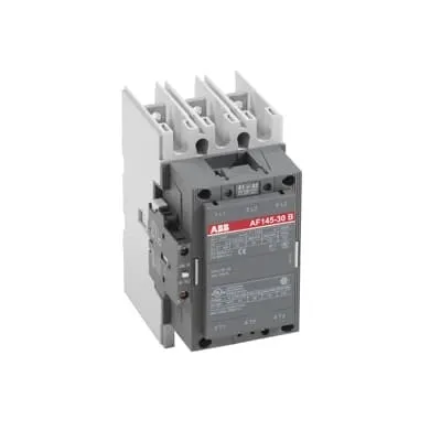
Block Contactor ABB 1SFL477062R6911 delivers reliable 3-pole switching for rail and industrial control. In demanding environments, engineers need a device that tolerates wide control voltage ranges and provides predictable coil response. This model supports a wide control voltage range of 48 to 130 V and 50/60 Hz, including DC, enabling a single part to cover multiple installations. It carries robust certifications to simplify compliance: IEC/EN 60947-4-1, UL 60947-4-1, and CE declarations, plus a suite of third‑party approvals (ABS, BV, GL, LR, RINA, RMRS) for global projects. The combination of a compact footprint, favorable weight, and strong mechanical durability supports predictable lifecycle costs and streamlined spares management. Secondary benefits include improved installation quality and reduced panel space for rail applications.
Product Information
Extended Description
1SFL477062R6911 ABB: A 3-phase Contactor suitable for Rail way applications application. Operated with a wide voltage control voltage range 48-60 V, 50/60Hz / DC
Minimum Order Quantity
1 piece
Customs Tariff Number
85364900
Replacement Product ID (NEW)
1SFL467062R1222
Data Sheet, Technical Information
1SBC100192C0206
Instructions and Manuals
Contactors A145, A185, A210, A260, A300
Dimension Diagram
53540923-7
Product Net Width
111.5 mm
Product Net Depth / Length
160 mm
Product Net Height
196 mm
Product Net Weight
3.3 kg
Number of Main Contacts NO
3
Number of Main Contacts NC
0
Number of Auxiliary Contacts NO
1
Number of Auxiliary Contacts NC
1
Number of Poles
3P
Standards
IEC/EN 60947-1, IEC/EN 60947-4-1, UL 60947-4-1, CSA C22.2 No. 60947-4-1, IEC 60077-1 (applicable parts), IEC 60077-2 (applicable parts), EN 50155 (applicable parts), TR CU 001/2011, IEC 61373, For compliance confirmation on applicable parts based on your application and combination, please consult your ABB sales representatives.
Rated Operational Voltage
Main Circuit 690 V
Rated Frequency (f)
Main Circuit 50 / 60 Hz
Conventional Free-air Thermal Current (Ith)
acc. to IEC 60947-4-1, Open Contactors Θ = 40 °C 250 A
Rated Operational Current AC-1 (Ie)
(1000 V) 40 °C 180 A | (1000 V) 55 °C 180 A | (1000 V) 70 °C 180 A | (690 V) 40 °C 250 A | (690 V) 55 °C 230 A | (690 V) 70 °C 180 A
Rated Operational Current AC-3 (Ie)
(415 V) 55 °C 145 A | (440 V) 55 °C 145 A | (500 V) 55 °C 145 A | (690 V) 55 °C 120 A | (1000 V) 55 °C 80 A | (380 / 400 V) 55 °C 145 A | (220 / 230 / 240 V) 55 °C 145
Rated Operational Current DC-1 (Ie)
(110 V) 2 Poles in Series, 40 °C 250 A | (220 V) 3 Poles in Series, 40 °C 250 A
Rated Operational Current DC-3 (Ie)
(110 V) 2 Poles in Series, 40 °C 250 A | (220 V) 3 Poles in Series, 40 °C 250 A
Rated Operational Current DC-5 (Ie)
(110 V) 2 Poles in Series, 40 °C 250 A | (220 V) 3 Poles in Series, 40 °C 250 A
Rated Operational Power AC-3 (Pe)
(415 V) 75 kW | (440 V) 75 kW | (500 V) 90 kW | (690 V) 110 kW | (1000 V) 110 kW | (380 / 400 V) 75 kW | (220 / 230 / 240 V) 45 kW
Rated Breaking Capacity AC-3
8 x Ie AC-3
Rated Making Capacity AC-3
10 x Ie AC-3
Short-Circuit Protective Devices
gG Type Fuses 160 A
Maximum Breaking Capacity
cos phi=0.45 (cos phi=0.35 for Ie > 100 A) at 440 V 1500 A | cos phi=0.45 (cos phi=0.35 for Ie > 100 A) at 690 V 1200 A
Rated Insulation Voltage (Ui)
acc. to IEC 60947-4-1 and VDE 0110 (Gr. C) 1000 V | acc. to UL/CSA 600 V
Rated Impulse Withstand Voltage (Uimp)
Main Circuit 8 kV
Maximum Electrical Switching Frequency
(AC-1) 300 cycles per hour | (AC-2 / AC-4) 150 cycles per hour | (AC-3) 300 cycles per hour
Mechanical Durability
5 million
Maximum Mechanical Switching Frequency
300 cycles per hour
Coil Operating Limits
(acc. to IEC 60947-4-1) 0.85 x Uc Min. ... 1.1 x Uc Max. (at θ ≤ 70 °C)
Rated Control Circuit Voltage (Uc)
50 Hz 48 ... 130 V | 60 Hz 48 ... 130 V | DC Operation 48 ... 130 V
Coil Consumption
Holding at Max. Rated Control Circuit Voltage 50 Hz 12 V·A | Holding at Max. Rated Control Circuit Voltage 60 Hz 12 V·A | Holding at Max. Rated Control Circuit Voltage DC 2 W | Pull-in at Max. Rated Control Circuit Voltage 50 Hz 430 V·A | Pull-in at Max. Rated Control Circuit Voltage 60 Hz 430 V·A | Pull-in at Max. Rated Control Circuit Voltage DC 500 W
Power Loss
at Rated Operating Conditions per Pole 5 W
Operate Time
Between Coil De-energization and NC Contact Closing 40 ... 50 ms | Between Coil De-energization and NO Contact Opening 43 ... 53 ms | Between Coil Energization and NC Contact Opening 45 ... 85 ms | Between Coil Energization and NO Contact Closing 50 ... 90 ms
Connecting Capacity Main Circuit
Bar 24 mm² | Rigid Al-Cable 1 x 25 ... 150 mm² | Rigid Cu-Cable 1 x 6 ... 185 mm²
Connecting Capacity Auxiliary Circuit
Flexible with Ferrule 1x 0.75 ... 2.5 mm² | Flexible with Insulated Ferrule 2x 0.75 ... 2.5 mm² | Flexible 1x0.75 ... 2.5 mm² | Solid 2 x 1 ... 4 mm² | Stranded 1 x 1 .... 4 mm²
Connecting Capacity
Bar 24 mm² | Rigid Al-Cable 1 x 25 ... 150 mm² | Rigid Cu-Cable 1 x 6 ... 185 mm²
Degree of Protection
acc. to IEC 60529, IEC 60947-1, EN 60529 Coil Terminals IP20 | acc. to IEC 60529, IEC 60947-1, EN 60529 Main Terminals IP00
Connecting Terminals (delivered in open position) Main Poles
Flat type c/w screws and bolts
Tightening Torque
Main Circuit 18 N·m
Terminal Type
Ring-Tongue Terminals
Product Name
Block Contactor
NEMA Size
4
Maximum Operating Voltage UL/CSA
Main Circuit 600 V
General Use Rating UL/CSA
(600 V AC) 230 A
Horsepower Rating UL/CSA
(200 V AC) Three Phase 40 hp | (208 V AC) Three Phase 40 hp | (220 ... 240 V AC) Three Phase 50 hp | (440 ... 480 V AC) Three Phase 100 hp | (550 ... 600 V AC) Three Phase 125 hp
Full Load Amps Motor Use
(440 ... 480 V AC) Three Phase 124 A | (550 ... 600 V AC) Three Phase 125 A
Ambient Air Temperature
Close to Contactor Fitted with Thermal O/L Relay (0.85 ... 1.1 Uc) -25 ... 50 °C | Close to Contactor without Thermal O/L Relay (0.85 ... 1.1 Uc) -40 ... 70 °C | Close to Contactor for Storage -40 ... 70 °C
Maximum Operating Altitude Permissible
Without Derating 3000 m
Resistance to Shock acc. to IEC 60068-2-27
Shock Direction: A 5 g | Shock Direction: B1 5 g | Shock Direction: B2 5 g | Shock Direction: C1 5 g | Shock Direction: C2 5 g
RoHS Information
CE Declaration of Conformity - Contactor - A(F)95...A(F)300, AM110...AM300, UA95...UA110, (T)AE95....(T)AE110
RoHS Status
Following EU Directive 2011/65/EU
WEEE B2C / B2B
Business To Business
WEEE Category
5. Small Equipment (No External Dimension More Than 50 cm)
ABS Certificate
ABS Certificate, Contactor, AF400...AF2050 (Sweden)
BV Certificate
13409/C0 BV
CB Certificate
SE-69478
CQC Certificate
CQC Certificate, Contactor, AF145, AF185, AF145B...RT, AF185B...RT, Made in Sweden
Declaration of Conformity - CCC
CCC Declaration of Conformity, Contactor, AF145, AF185, AF145B...RT, AF185B...RT, Made in Sweden
Declaration of Conformity - CE
CE Declaration of Conformity - Contactor - A(F)95...A(F)300, AM110...AM300, UA95...UA110, (T)AE95....(T)AE110
EAC Certificate
9AKK107046A8618
GL Certificate
GL_20261-04HH
LOVAG Certificate
SE-0105160
LR Certificate
LR_04-00015-E1
RINA Certificate
ELE060313XG/002
RMRS Certificate
RMRS_12-03683-315
Package Level 1 Units
box 1 piece
Package Level 1 Width
178 mm
Package Level 1 Depth / Length
232 mm
Package Level 1 Height
167 mm
Package Level 1 Gross Weight
3.5 kg
Package Level 1 EAN
7320500260289
Object Classification Code
Q
ETIM 7
EC000066 - Power contactor, AC switching
ETIM 8
EC000066 - Power contactor, AC switching
ETIM 9
EC000066 - Power contactor, AC switching
eClass
V11.0 : 27371003
UNSPSC
39121529
IDEA Granular Category Code (IGCC)
4755 >> Contactors
Feature: Three main normally open contacts plus one normally open and one normally closed auxiliary contact provide expanded control and status feedback, enabling tighter interlocks and simpler wiring. Business Impact: Reduces component count, lowers panel complexity, and improves fault diagnostics in motor control centers. Application: Ideal for conveyor drives and traction-related equipment in rail and light industrial systems. Feature: Coil operating range 48–130 V across 50/60 Hz and DC supports versatile installations with a single part number. Business Impact: Simplifies procurement, minimizes stocking of voltage variants, and accelerates commissioning. Application: Control circuits in mixed-voltage environments without re-wiring. Feature: Rated operational current AC-3 up to 145 A at typical voltages and 250 A main circuit capability at lower control voltages. Business Impact: Higher load-handling capability reduces soft-start devices and lowers total cost of ownership. Application: Medium-power motor switching in pumps, fans, and conveyors. Feature: Mechanical durability rated at 5 million cycles and a maximum switching frequency of 300 cycles per hour. Business Impact: Extends product life in high-cycle environments, reducing maintenance windows. Application: Frequent-relay duty in rolling stock and manufacturing lines. Feature: Robust protection and versatile connection options including Bar, rigid Al-Cable, and Cu-Cable terminations plus flexible cable connections. Business Impact: Eases installation, improves reliability, and speeds up wiring harness assembly. Application: Industrial control panels and machine builds requiring adaptable conductor interfaces.
Get a Quick Quote for a ABB 1SFL477062R6911
Chat with us on WhatsApp - fast responses guaranteed
Need to speak with someone? We'll call you back within 2 hours during business hours
Interested in ABB 1SFL477062R6911?
Enquire Now
FAQs
The ABB 1SFL477062R6911 supports a wide control voltage range of 48 to 130 V across AC, 50/60 Hz, and DC operation as specified. This enables a single converter to cover multiple regional control voltages, reducing stocking and wiring complexity while maintaining reliable pull-in and holding characteristics.
Yes, this 3-pole block contactor is designed for railway-related control with IEC/EN 60947-4-1 compliance and UL 60947-4-1, plus CE declarations. It also carries additional third‑party certifications (ABS, BV, GL, LR, RINA, RMRS) to support global rail projects and ensure regulatory alignment.
Key ratings include main circuit voltage up to 690 V and AC-3 operating current up to 145 A at 440–690 V, with 180–250 A at lower voltages in AC-1 or DC conditions. The device also provides an 8 kV impulse withstand and a 1000 V insulation voltage, suitable for demanding motor control tasks.
Connection options include bar-type terminals for 24 mm² main conductors, rigid Al-Cable up to 150 mm², and copper up to 185 mm². Auxiliary circuits support flexible ferrule and solid conductors from 0.75 to 4 mm². Tightening torque for main circuits is 18 N·m, ensuring secure and durable connections in panel builds.
With a mechanical durability of 5 million cycles and a maximum switching frequency of 300 cycles per hour, the device supports high-cycle environments. Regular inspection of terminations, verification of coil voltage within 48–130 V, and monitoring for signs of wear in auxiliary contacts help sustain reliable operation and minimize unplanned downtime.