ABB 1SFL477062R7211 Block Contactor - IEC 60947-4-1
Part Number: 1SFL477062R7211
Quick Summary
ABB 1SFL477062R7211 block contactor is a three-pole device for railway drive systems, delivering reliable motor control in demanding environments. With voltage variability and tight panel space, its 20–60 V DC coil and compact form simplify installation. Key certifications such as IEC/EN 60947-4-1, UL 60947-4-1, and CE markings support rail compliance. Its compact footprint and robust construction facilitate standard mounting with ring-tongue terminals, reducing wiring labor and lifecycle costs. This combination also aligns with 5 million mechanical cycles and IP protection features, delivering long-term reliability for rail OEMs and service teams. Engineers gain a proven, maintenance-friendly solution that scales across equipment platforms while meeting stringent safety and regulatory requirements.
Product Information
Extended Description
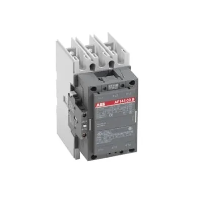
1SFL477062R7211 ABB: A 3-phase Contactor suitable for Rail way applications application. Operated with a wide voltage control voltage range 20-60V, DC
Minimum Order Quantity
1 piece
Customs Tariff Number
85364900
Replacement Product ID (NEW)
1SFL467062R1122
Data Sheet, Technical Information
1SBC100192C0206
Instructions and Manuals
Contactors A145, A185, A210, A260, A300
Dimension Diagram
53540923-7
Product Net Width
111.5 mm
Product Net Depth / Length
160 mm
Product Net Height
196 mm
Product Net Weight
3.3 kg
Number of Main Contacts NO
3
Number of Main Contacts NC
0
Number of Auxiliary Contacts NO
1
Number of Auxiliary Contacts NC
1
Number of Poles
3P
Standards
IEC/EN 60947-1, IEC/EN 60947-4-1, UL 60947-4-1, CSA C22.2 No. 60947-4-1, IEC 60077-1 (applicable parts), IEC 60077-2 (applicable parts), EN 50155 (applicable parts), TR CU 001/2011, IEC 61373, For compliance confirmation on applicable parts based on your application and combination, please consult your ABB sales representatives.
Rated Operational Voltage
Main Circuit 690 V
Conventional Free-air Thermal Current (Ith)
acc. to IEC 60947-4-1, Open Contactors Θ = 40 °C 250 A
Rated Operational Current AC-1 (Ie)
(1000 V) 40 °C 180 A | (1000 V) 55 °C 180 A | (1000 V) 70 °C 180 A | (690 V) 40 °C 250 A | (690 V) 55 °C 230 A | (690 V) 70 °C 180 A
Rated Operational Current AC-3 (Ie)
(415 V) 55 °C 145 A | (440 V) 55 °C 145 A | (500 V) 55 °C 145 A | (690 V) 55 °C 120 A | (1000 V) 55 °C 80 A | (380 / 400 V) 55 °C 145 A | (220 / 230 / 240 V) 55 °C 145
Rated Operational Current DC-1 (Ie)
(110 V) 2 Poles in Series, 40 °C 250 A | (220 V) 3 Poles in Series, 40 °C 250 A
Rated Operational Current DC-3 (Ie)
(110 V) 2 Poles in Series, 40 °C 250 A | (220 V) 3 Poles in Series, 40 °C 250 A
Rated Operational Current DC-5 (Ie)
(110 V) 2 Poles in Series, 40 °C 250 A | (220 V) 3 Poles in Series, 40 °C 250 A
Rated Operational Power AC-3 (Pe)
(415 V) 75 kW | (440 V) 75 kW | (500 V) 90 kW | (690 V) 110 kW | (1000 V) 110 kW | (380 / 400 V) 75 kW | (220 / 230 / 240 V) 45 kW
Rated Breaking Capacity AC-3
8 x Ie AC-3
Rated Making Capacity AC-3
10 x Ie AC-3
Short-Circuit Protective Devices
gG Type Fuses 160 A
Maximum Breaking Capacity
cos phi=0.45 (cos phi=0.35 for Ie > 100 A) at 440 V 1500 A | cos phi=0.45 (cos phi=0.35 for Ie > 100 A) at 690 V 1200 A
Rated Insulation Voltage (Ui)
acc. to IEC 60947-4-1 and VDE 0110 (Gr. C) 1000 V | acc. to UL/CSA 600 V
Rated Impulse Withstand Voltage (Uimp)
Main Circuit 8 kV
Maximum Electrical Switching Frequency
(AC-1) 300 cycles per hour | (AC-2 / AC-4) 150 cycles per hour | (AC-3) 300 cycles per hour
Mechanical Durability
5 million
Maximum Mechanical Switching Frequency
300 cycles per hour
Coil Operating Limits
(acc. to IEC 60947-4-1) 0.85 x Uc Min. ... 1.1 x Uc Max. (at θ ≤ 70 °C)
Rated Control Circuit Voltage (Uc)
DC Operation 20 ... 60 V
Coil Consumption
Holding at Max. Rated Control Circuit Voltage 50 Hz 12 V·A | Holding at Max. Rated Control Circuit Voltage 60 Hz 12 V·A | Holding at Max. Rated Control Circuit Voltage DC 2 W | Pull-in at Max. Rated Control Circuit Voltage 50 Hz 430 V·A | Pull-in at Max. Rated Control Circuit Voltage 60 Hz 430 V·A | Pull-in at Max. Rated Control Circuit Voltage DC 500 W
Power Loss
at Rated Operating Conditions per Pole 5 W
Operate Time
Between Coil De-energization and NC Contact Closing 40 ... 50 ms | Between Coil De-energization and NO Contact Opening 43 ... 53 ms | Between Coil Energization and NC Contact Opening 45 ... 85 ms | Between Coil Energization and NO Contact Closing 50 ... 90 ms
Connecting Capacity Main Circuit
Bar 24 mm² | Rigid Al-Cable 1 x 25 ... 150 mm² | Rigid Cu-Cable 1 x 6 ... 185 mm²
Connecting Capacity Auxiliary Circuit
Flexible with Ferrule 1x 0.75 ... 2.5 mm² | Flexible with Insulated Ferrule 2x 0.75 ... 2.5 mm² | Flexible 2x0.75 ... 2.5 mm² | Solid 2 x 1 ... 4 mm² | Stranded 2 x 1 .... 4 mm²
Connecting Capacity
Bar 24 mm² | Rigid Al-Cable 1 x 25 ... 150 mm² | Rigid Cu-Cable 1 x 6 ... 185 mm²
Degree of Protection
acc. to IEC 60529, IEC 60947-1, EN 60529 Coil Terminals IP20 | acc. to IEC 60529, IEC 60947-1, EN 60529 Main Terminals IP00
Connecting Terminals (delivered in open position) Main Poles
Flat type c/w screws and bolts
Tightening Torque
Main Circuit 18 N·m
Terminal Type
Ring-Tongue Terminals
Product Name
Block Contactor
NEMA Size
4
Maximum Operating Voltage UL/CSA
Main Circuit 600 V
General Use Rating UL/CSA
(600 V AC) 230 A
Horsepower Rating UL/CSA
(200 V AC) Three Phase 40 hp | (208 V AC) Three Phase 40 hp | (220 ... 240 V AC) Three Phase 50 hp | (440 ... 480 V AC) Three Phase 100 hp | (550 ... 600 V AC) Three Phase 125 hp
Full Load Amps Motor Use
(440 ... 480 V AC) Three Phase 124 A | (550 ... 600 V AC) Three Phase 125 A
Ambient Air Temperature
Close to Contactor Fitted with Thermal O/L Relay (0.85 ... 1.1 Uc) -25 ... 50 °C | Close to Contactor without Thermal O/L Relay (0.85 ... 1.1 Uc) -40 ... 70 °C | Close to Contactor for Storage -40 ... 70 °C
Maximum Operating Altitude Permissible
Without Derating 3000 m
Resistance to Shock acc. to IEC 60068-2-27
Shock Direction: A 5 g | Shock Direction: B1 5 g | Shock Direction: B2 5 g | Shock Direction: C1 5 g | Shock Direction: C2 5 g
RoHS Information
CE Declaration of Conformity - Contactor - A(F)95...A(F)300, AM110...AM300, UA95...UA110, (T)AE95....(T)AE110
RoHS Status
Following EU Directive 2011/65/EU
WEEE B2C / B2B
Business To Business
WEEE Category
5. Small Equipment (No External Dimension More Than 50 cm)
ABS Certificate
ABS Certificate, Contactor, AF400...AF2050 (Sweden)
BV Certificate
13409/C0 BV
CB Certificate
SE-69478
CQC Certificate
CQC Certificate, Contactor, AF145, AF185, AF145B...RT, AF185B...RT, Made in Sweden
Declaration of Conformity - CCC
CCC Declaration of Conformity, Contactor, AF145, AF185, AF145B...RT, AF185B...RT, Made in Sweden
Declaration of Conformity - CE
CE Declaration of Conformity - Contactor - A(F)95...A(F)300, AM110...AM300, UA95...UA110, (T)AE95....(T)AE110
EAC Certificate
9AKK107046A8618
GL Certificate
GL_20261-04HH
LOVAG Certificate
SE-0105160
LR Certificate
LR_04-00015-E1
RINA Certificate
ELE060313XG/002
RMRS Certificate
RMRS_12-03683-315
TÜV Certificate
MHM-EST-7.70017788e
Package Level 1 Units
box 1 piece
Package Level 1 Width
178 mm
Package Level 1 Depth / Length
232 mm
Package Level 1 Height
167 mm
Package Level 1 Gross Weight
3.5 kg
Package Level 1 EAN
7320500260265
Object Classification Code
Q
ETIM 7
EC000066 - Power contactor, AC switching
ETIM 8
EC000066 - Power contactor, AC switching
ETIM 9
EC000066 - Power contactor, AC switching
eClass
V11.0 : 27371003
UNSPSC
39121529
IDEA Granular Category Code (IGCC)
4755 >> Contactors
Feature: Three-pole block construction with 3 main NO contacts and 1 NO/1 NC auxiliary contact. Business Impact: Enables compact, high-current switching for multi-phase loads while preserving control circuit clarity. Application: Drives and signaling in rail and industrial automation where space is at a premium and reliability is critical. Feature: DC coil operating range of 20–60 V. Business Impact: Flexible control logic compatible with various DC control architectures, reducing interface complexity. Application: Rail propulsion panels and control cabinets where supply voltages vary. Feature: Main circuit rated up to 690 V with AC-3 current up to 145 A (and higher DC ratings in series configurations). Business Impact: Supports demanding motor starting and braking tasks without oversizing components. Application: Primary drive circuits and auxiliary drives in rolling stock. Feature: Power and thermal performance — 5 W per pole power loss with 12 V·A holding/430 V·A pull-in values. Business Impact: Predictable heat output and energy efficiency, lowering cooling requirements. Application: Continuous operation in enclosed switchgear. Feature: Mechanical durability rated at 5 million cycles. Business Impact: Longer maintenance intervals and lower lifecycle cost. Application: High-cycle signaling and control panels in rail environments. Feature: IP20 coil terminals and IP00 main terminals with robust ring-tongue and screw-terminal connections. Business Impact: Safer, reliable wiring and faster installation with common terminal practices. Application: Field installations in rugged environments. Feature: Short-circuit protection using gG type fuses (160 A). Business Impact: Enhanced protection against fault currents, improving system uptime. Application: Protection schemes in traction and auxiliary power circuits. Feature: Compliance with standards including IEC 60947-1/4-1, UL/CSA, CE and EN 50155. Business Impact: Regulatory peace of mind for new builds and retrofit programs. Application: Rail OEMs seeking certified, globally recognizable components.
Get a Quick Quote for a ABB 1SFL477062R7211
Chat with us on WhatsApp - fast responses guaranteed
Need to speak with someone? We'll call you back within 2 hours during business hours
Interested in ABB 1SFL477062R7211?
Enquire Now
FAQs
Mount the unit using standard 24 mm² busbar connections or ring-tongue terminals as shipped. Tighten main terminals to 18 N·m and ensure coil terminals are protected with IP20 sealing. The device supports a compact footprint with 111.5 mm width, 160 mm depth, and 196 mm height for straightforward panel integration.
Rated Operational Current AC-3 is up to 145 A at 415–690 V and up to 180 A at certain tolerances, with DC ratings of 250 A in appropriate configurations (2 poles in series for DC-1/3/5). The main circuit voltage goes up to 690 V, and the coil control voltage is 20–60 V DC.
Yes. It is designed for rail applications and supports up to 3000 m altitude without derating. It provides robust operation across -25 to 50 °C ambient with considerations for coil O/L relay, and storage conditions extend to -40 to 70 °C, meeting environmental and safety requirements for rail systems.
It complies with IEC/EN 60947-1 and IEC 60947-4-1, and UL/CSA 60947-4-1. Additional endorsements include CE, EN 50155, IEC 61373, and other global certificates (EAC, TÜV, GL, ABS) to support compliance in diverse markets and rail OEM programs.
With a mechanical durability rating of 5 million cycles and a modular design that supports standard terminal connections, it reduces spare-part complexity and maintenance downtime. Auxiliary contacts (NO/NC) improve signaling reliability, while the gG fuse compatibility protects circuits, contributing to lower total cost of ownership in rail applications.