ABB 1SFL487002R3111 Contactor - 1000 V AC-3e 190 A
Part Number: 1SFL487002R3111
Quick Summary
ABB 1SFL487002R3111 Contactor is a three-pole motor-contactor designed for reliable starting and stopping of large AC motors in industrial environments. In modern panels, voltage and control-circuit fluctuations can cause missed starts and nuisance trips, adding downtime and maintenance costs. This device carries CE and UKCA declarations, UL/CSA approvals, and IP ratings for both coil and main terminals, supporting regulatory compliance and safe operation. Coupled with AF technology and easy expansion with auxiliary contact blocks, it delivers compact, energy-efficient motor control with scalable protection. Its wide control voltage range, 24–60 V AC and 20–60 V DC, reduces panel power waste while maintaining reliable operation across unstable networks.
Product Information
Extended Description
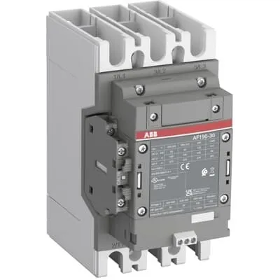
1SFL487002R3111 ABB: The AF190-30-11-31 is a 3 pole - 1000 V IEC or 600 V UL contactor with Main Circuit Bars, controlling motors up to 90 kW / 400 V AC (AC-3) or 125 hp / 480 V UL and switching power circuits up to 275 A (AC-1) or 250 A UL general use. Thanks to the AF technology, the contactor has a wide control voltage range (24-60 V 50/60 Hz and 20-60 V DC), managing large control voltage variations, reducing panel energy consumptions and ensuring distinct operations in unstable networks. Furthermore, surge protection is built-in, offering a compact solution. AF contactors have a block type design, can be easily extended with add-on auxiliary contact blocks and an additional wide range of accessories.
Minimum Order Quantity
1 piece
Customs Tariff Number
8536490099
Data Sheet, Technical Information
1SBC100214C0202 - Main catalog Motor protection and control Manual motor starters, contactors and overload relays (PDF) - Edition 2024
Data Sheet, Technical Information (Part 2)
Contactors and Overload relays guide
Instructions and Manuals
Operating instruction, Contactor, AF(S)190 ... AF(S)370
CAD Dimensional Drawing
Information - 2D and 3D files for CAD systems
Product Net Width
105 mm
Product Net Depth / Length
165.5 mm
Product Net Height
196 mm
Product Net Weight
2.4 kg
Number of Main Contacts NO
3
Number of Main Contacts NC
0
Number of Auxiliary Contacts NO
1
Number of Auxiliary Contacts NC
1
Number of Poles
3P
Rated Operational Voltage
Main Circuit 1000 V
Rated Frequency (f)
Main Circuit 50 / 60 Hz
Conventional Free-air Thermal Current (Ith)
acc. to IEC 60947-4-1, Open Contactors Θ = 40 °C 275 A
Rated Operational Current AC-1 (Ie)
(1000 V) 40 °C 250 A | (1000 V) 60 °C 225 A | (1000 V) 70 °C 185 A | (690 V) 40 °C 275 A | (690 V) 60 °C 250 A | (690 V) 70 °C 200 A
Rated Operational Current AC-3 (Ie)
(415 V) 60 °C 190 A | (440 V) 60 °C 190 A | (500 V) 60 °C 156 A | (690 V) 60 °C 135 A | (1000 V) 60 °C 85 A | (380 / 400 V) 60 °C 190 A | (220 / 230 / 240 V) 60 °C 190 A
Rated Operational Current AC-3e (Ie)
(415 V) 60 °C 190 A | (440 V) 60 °C 190 A | (500 V) 60 °C 135 A | (690 V) 60 °C 135 A | (1000 V) 60 °C 85 A | (380 / 400 V) 60 °C 190 A | (220 / 230 / 240 V) 60 °C 190 A
Rated Operational Power AC-3 (Pe)
(415 V) 90 kW | (440 V) 110 kW | (500 V) 110 kW | (690 V) 132 kW | (1000 V) 110 kW | (380 / 400 V) 90 kW | (220 / 230 / 240 V) 55 kW
Rated Operational Power AC-3e (Pe)
(415 V) 90 kW | (440 V) 110 kW | (500 V) 110 kW | (690 V) 132 kW | (1000 V) 110 kW | (380 / 400 V) 90 kW | (220 / 230 / 240 V) 55 kW
Rated Breaking Capacity AC-3
8 x Ie AC-3
Rated Breaking Capacity AC-3e
8.5 x Ie AC-3e
Rated Making Capacity AC-3
10 x Ie AC-3
Rated Making Capacity AC-3e
12 x Ie AC-3e
Rated Short-time Withstand Current Low Voltage (Icw)
at 40 °C Ambient Temp, in Free Air, from a Cold State 10 s 1520 A | at 40 °C Ambient Temp, in Free Air, from a Cold State 15 min 275 A | at 40 °C Ambient Temp, in Free Air, from a Cold State 1 min 621 A | at 40 °C Ambient Temp, in Free Air, from a Cold State 1 s 1900 A | at 40 °C Ambient Temp, in Free Air, from a Cold State 30 s 878 A
Maximum Breaking Capacity
cos phi=0.45 (cos phi=0.35 for Ie > 100 A) at 440 V 3300 A | cos phi=0.45 (cos phi=0.35 for Ie > 100 A) at 690 V 2200 A
Rated Insulation Voltage (Ui)
acc. to IEC 60947-4-1 and VDE 0110 (Gr. C) 1000 V | acc. to UL/CSA 1000 V
Rated Impulse Withstand Voltage (Uimp)
Main Circuit 8 kV
Maximum Electrical Switching Frequency
(AC-1) 300 cycles per hour | (AC-2 / AC-4) 150 cycles per hour | (AC-3) 300 cycles per hour
Mechanical Durability
5 million
Maximum Mechanical Switching Frequency
300 cycles per hour
Rated Control Circuit Voltage (Uc)
50 Hz 24 ... 60 V | 60 Hz 24...60 V | DC Operation 20...60 V
Coil Consumption
Holding at Max. Rated Control Circuit Voltage 50 Hz 5 V·A | Holding at Max. Rated Control Circuit Voltage 50 Hz 3 W | Holding at Max. Rated Control Circuit Voltage 60 Hz 5 V·A | Holding at Max. Rated Control Circuit Voltage 60 Hz 3 W | Holding at Max. Rated Control Circuit Voltage DC 2.5 W | Pull-in at Max. Rated Control Circuit Voltage 50 Hz 165 V·A | Pull-in at Max. Rated Control Circuit Voltage 60 Hz 165 V·A | Pull-in at Max. Rated Control Circuit Voltage DC 205 W
Power Loss
at Rated Operating Conditions AC-1 per Pole 15 W | at Rated Operating Conditions AC-3 per Pole 7 W
Operate Time
Between Coil De-energization and NO Contact Opening 45 ... 80 ms | Between Coil Energization and NO Contact Closing 25 ... 60 ms
Connecting Capacity Auxiliary Circuit
Flexible with Ferrule 1x 0.75 ... 2.5 mm² | Flexible with Ferrule 2x 0.75 ... 2.5 mm² | Flexible with Insulated Ferrule 1x 0.75 ... 2.5 mm² | Flexible with Insulated Ferrule 2x 0.75 ... 2.5 mm² | Flexible 1x 0.75 ... 2.5 mm² | Flexible 2x 0.75 ... 2.5 mm² | Solid 1x 1 ... 4 mm² | Solid 2x 1 ... 4 mm² | Stranded 1x 1 ... 4 mm² | Stranded 2x 1 ... 4 mm²
Connecting Capacity
Flexible 2 x 50 ... 95 mm² | Rigid Al-Cable 1 x 95 ... 185 mm² | Rigid Cu-Cable 1 x 6 ... 150 mm²
Wire Stripping Length
Auxiliary Circuit 9 mm | Control Circuit 9 mm
Degree of Protection
acc. to IEC 60529, IEC 60947-1, EN 60529 Coil Terminals IP20 | acc. to IEC 60529, IEC 60947-1, EN 60529 Main Terminals IP00
Recommended Screw Driver
Main Circuit M8 | Control Circuit M3.5
Tightening Torque
Auxiliary Circuit 1 N·m | Cable Lug 18 N·m | Control Circuit 1 N·m | Main Circuit 14 ... 31 N·m
Terminal Type
Main Circuit: Bars
Product Name
Block Contactor
Maximum Operating Voltage UL/CSA
Main Circuit 1000 V
General Use Rating UL/CSA
(1000 V AC) 250 A
Horsepower Rating UL/CSA
(200 ... 208 V AC) Three Phase 50 hp | (220 ... 240 V AC) Three Phase 60 hp | (440 ... 480 V AC) Three Phase 125 hp | (550 ... 600 V AC) Three Phase 150 hp
Tightening Torque UL/CSA
Auxiliary Circuit 9 in·lb | Control Circuit 9 in·lb | Main Circuit 301 in·lb
Full Load Amps Motor Use
(200 ... 208 V AC) Three Phase 150 A | (220 ... 240 V AC) Three Phase 154 A | (440 ... 480 V AC) Three Phase 156 A | (550 ... 600 V AC) Three Phase 144 A
Ambient Air Temperature
Close to Contactor Fitted with Thermal O/L Relay (0.85 ... 1.1 Uc) -25 ... 55 °C | Close to Contactor without Thermal O/L Relay (0.85 ... 1.1 Uc) -40 ... 70 °C | Close to Contactor for Storage -40 ... 70 °C
Maximum Operating Altitude Permissible
Without Derating 3000 m
Conflict Minerals Reporting Template (CMRT)
CMRT - Conflict Minerals Reporting Template
REACH Declaration
REACH - Letter of Confirmation for block contactors, contactor relays, installation contactors, mini contactors, mini contactor relays, thermal overload relays, electronic overload relays and related accessories
RoHS Information
RoHS II declaration for block contactors, installation contactors, mini contactors, mini contactor relays, thermal overload relays, electronic overload relays and related accessories
RoHS Status
Following EU Directive 2011/65/EU and Amendment 2015/863 July 22, 2019
Toxic Substances Control Act - TSCA
Toxic Substances Control Act (TSCA) declaration for Contactors
WEEE B2C / B2B
Business To Business
WEEE Category
5. Small Equipment (No External Dimension More Than 50 cm)
ABB EcoSolutions
Yes
ABB Site Meeting Group Waste To Landfill Target
Non-hazardous waste is sent to a landfill, where there is no alternative option available within 100km of a facility
End Of Life Disassembling Instructions
End-of-life instruction - AF(S)116(B)-**(RT) to AF(S)205(B)-**(RT)
Environmental Product Declaration - EPD
Environmental Product Declaration, AF190-AF205 (SE) Contactors
Improved Energy Efficiency for Customers
Product Efficiency - Product requires less energy to operate compared to similar product on market or older products from the same line
Recyclability Rate of the Product acc. to EN45555
Design for Closing Resource Loops - Standard EN45555 - 79.2 %
Sustainable Material Content in Product (wt. %)
Recycled Metal - 35 %
A2L Certificate – UL
UL Certificate of Compliance A2L, Contactor, AF190 - AF370
Declaration of Conformity - CE
CE Declaration of Conformity - Contactor - AF116...AF370
Declaration of Conformity - UKCA
UK Declaration of Conformity - Contactors >100A
UL Certificate
cULus Certificate, Contactor, AF190-30, AF205-30, AFS190-30, AFS205-30
Package Level 1 Units
box 1 piece
Package Level 1 Width
160 mm
Package Level 1 Depth / Length
258 mm
Package Level 1 Height
235 mm
Package Level 1 Gross Weight
3 kg
Package Level 1 EAN
7320500561669
Object Classification Code
Q
ETIM 7
EC000066 - Power contactor, AC switching
ETIM 8
EC000066 - Power contactor, AC switching
ETIM 9
EC000066 - Power contactor, AC switching
eClass
V11.0 : 27371003
UNSPSC
39121529
IDEA Granular Category Code (IGCC)
4758 >> Iec Contactors
AF technology and wide coil range deliver stable operation across varying networks, reducing nuisance trips and energy waste while simplifying design choices for panel builders. The three main NO contacts plus one NO and one NC auxiliary contact support robust motor control and interlocking schemes, enabling straightforward integration with add-on auxiliary blocks for future expansion. The AF design enables broad control voltage compatibility, allowing 24–60 V AC or 20–60 V DC control signals to drive the same hardware, minimizing inventory and simplifying spare parts. Rated for up to 1000 V main circuit, it supports AC-1 and AC-3 duty with currents up to 250 A and 190 A respectively, delivering high reliability for pumps, conveyors, and fans in medium-load applications. Built-in surge protection reduces panel complexity and improves safety by limiting voltage spikes. The block-contactor form factor simplifies wiring and maintenance, while the ability to extend with accessory blocks supports scalable protection and interlocking strategies for complex motor drives. This combination delivers measurable gains in energy efficiency, reliability, and lifecycle cost for industrial automation projects. In addition, the device is designed for easy installation with standard mounting, conventional tightening torques, and compatible CAD resources, accelerating project timelines and reducing commissioning risk.
Get a Quick Quote for a ABB 1SFL487002R3111
Chat with us on WhatsApp - fast responses guaranteed
Need to speak with someone? We'll call you back within 2 hours during business hours
Interested in ABB 1SFL487002R3111?
Enquire Now
FAQs
This 3-pole block contactor uses main circuit bars and accepts add-on auxiliary contact blocks. Use the recommended tightening torques: main circuit 14–31 N·m, auxiliary circuit 1 N·m, control circuit 1 N·m, and cable lugs 18 N·m. Wire sizes include flexible 2x50–95 mm² or solid 1–4 mm² for auxiliary and control circuits. Ensure IP20 protection for coil terminals and IP00 for main terminals, and verify control voltage is within 24–60 V AC or 20–60 V DC per your design. CAD drawings and manuals are available for proper installation and interlock alignment.
For AC-1, Ie values reach up to 250 A at 1000 V (decreasing with higher ambient temperatures). For AC-3, Ie is 190 A at several voltages (e.g., 415–690 V) with corresponding Pe up to 132 kW at 690 V. The device also accommodates AC-3e ratings with similar Ie values. These ratings enable reliable motor starting and running in mid- to high-power applications such as pumps, conveyors, and fans.
Yes. The contactor features Rated Insulation Voltage Ui of 1000 V, Rated Impulse Withstand Voltage Uimp of 8 kV, and General Use UL/CSA ratings up to 1000 V. It also includes UL certificates and CE/UKCA declarations, ensuring compliance for UL/CSA environments and cross-border installations.
The coil accepts 24–60 V at 50 Hz or 60 Hz, and 20–60 V DC operation. Coil consumption varies with condition: holding at max voltage ranges from 3–5 W (AC), while pull-in values reach up to 165 V·A (AC) or 205 W (DC). This supports stable operation across fluctuating control signals, reducing the risk of mis-operation in unstable power networks.
CE Declaration of Conformity, UKCA, and UL/CSA certifications accompany IP20 coil protection and IP00 main terminal protection. Environmental declarations cover REACH, RoHS, and EPD disclosures, with documented end-of-life instructions and recyclable content. It is designed for 0 to 70 °C operation without a thermal overload relay and up to 3000 m altitude without derating.