ABB AF190-30-11-43 Contactor - IEC/UL 1000 V Ready
Part Number: 1SFL487002R4311
Quick Summary
ABB AF190-30-11-43 Contactor is a 3-pole power control device designed to switch and protect motors in demanding industrial environments. It delivers reliable motor control up to 90 kW at 400 V AC (AC-3) and 125 hp at UL, while supporting AC-1 and general use switching. When panel space and energy efficiency are tight, this AF technology-based contactor helps reduce energy consumption and accelerates operation times thanks to faster coil response and built-in surge protection. The product carries CE, UL/cUL, and UKCA certifications, along with RoHS and REACH declarations, ensuring compliance across major markets. This combination of performance, scalability, and regulatory alignment translates into lower lifecycle costs and healthier total cost of ownership for your automation stack.
Product Information
Extended Description
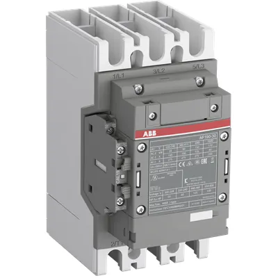
1SFL487002R4311 ABB: The AF190-30-11-43 is a 3 pole - 1000 V IEC or 600 V UL contactor with Main Circuit Bars, controlling motors up to 90 kW / 400 V AC (AC-3) or 125 hp / 480 V UL and switching power circuits up to 275 A (AC-1) or 250 A UL general use. Thanks to the AF technology, the contactor has a control voltage range (220-240 V 50/60 Hz),faster operation time, reducing panel energy consumptions and ensuring distinct operations in unstable networks. Furthermore, surge protection is built-in, offering a compact solution. AF contactors have a block type design, can be easily extended with add-on auxiliary contact blocks and an additional wide range of accessories.
Minimum Order Quantity
1 piece
Customs Tariff Number
8536490099
Data Sheet, Technical Information
1SBC100214C0202 - Main catalog Motor protection and control Manual motor starters, contactors and overload relays (PDF) - Edition 2024
Data Sheet, Technical Information (Part 2)
Contactors and Overload relays guide
Instructions and Manuals
Operating instruction, Contactor, AF(S)190 ... AF(S)370
CAD Dimensional Drawing
Information - 2D and 3D files for CAD systems
Product Net Width
105 mm
Product Net Depth / Length
152 mm
Product Net Height
196 mm
Product Net Weight
2.4 kg
Number of Main Contacts NO
3
Number of Main Contacts NC
0
Number of Auxiliary Contacts NO
1
Number of Auxiliary Contacts NC
1
Number of Poles
3P
Rated Operational Voltage
Main Circuit 1000 V
Rated Frequency (f)
Main Circuit 50 / 60 Hz
Conventional Free-air Thermal Current (Ith)
acc. to IEC 60947-4-1, Open Contactors Θ = 40 °C 275 A
Rated Operational Current AC-1 (Ie)
(1000 V) 40 °C 250 A | (1000 V) 60 °C 225 A | (1000 V) 70 °C 185 A | (690 V) 40 °C 275 A | (690 V) 60 °C 250 A | (690 V) 70 °C 200 A
Rated Operational Current AC-3 (Ie)
(415 V) 60 °C 190 A | (440 V) 60 °C 190 A | (500 V) 60 °C 156 A | (690 V) 60 °C 135 A | (1000 V) 60 °C 85 A | (380 / 400 V) 60 °C 190 A | (220 / 230 / 240 V) 60 °C 190 A
Rated Operational Current AC-3e (Ie)
(415 V) 60 °C 190 A | (440 V) 60 °C 190 A | (500 V) 60 °C 135 A | (690 V) 60 °C 135 A | (1000 V) 60 °C 85 A | (380 / 400 V) 60 °C 190 A | (220 / 230 / 240 V) 60 °C 190 A
Rated Operational Power AC-3 (Pe)
(415 V) 90 kW | (440 V) 110 kW | (500 V) 110 kW | (690 V) 132 kW | (1000 V) 110 kW | (380 / 400 V) 90 kW | (220 / 230 / 240 V) 55 kW
Rated Operational Power AC-3e (Pe)
(415 V) 90 kW | (440 V) 110 kW | (500 V) 110 kW | (690 V) 132 kW | (1000 V) 110 kW | (380 / 400 V) 90 kW | (220 / 230 / 240 V) 55 kW
Rated Breaking Capacity AC-3
8 x Ie AC-3
Rated Breaking Capacity AC-3e
8.5 x Ie AC-3e
Rated Making Capacity AC-3
10 x Ie AC-3
Rated Making Capacity AC-3e
12 x Ie AC-3e
Rated Short-time Withstand Current Low Voltage (Icw)
at 40 °C Ambient Temp, in Free Air, from a Cold State 10 s 1520 A | at 40 °C Ambient Temp, in Free Air, from a Cold State 15 min 275 A | at 40 °C Ambient Temp, in Free Air, from a Cold State 1 min 621 A | at 40 °C Ambient Temp, in Free Air, from a Cold State 1 s 1900 A | at 40 °C Ambient Temp, in Free Air, from a Cold State 30 s 878 A
Maximum Breaking Capacity
cos phi=0.45 (cos phi=0.35 for Ie > 100 A) at 440 V 3300 A | cos phi=0.45 (cos phi=0.35 for Ie > 100 A) at 690 V 2200 A
Rated Insulation Voltage (Ui)
acc. to IEC 60947-4-1 and VDE 0110 (Gr. C) 1000 V | acc. to UL/CSA 1000 V
Rated Impulse Withstand Voltage (Uimp)
Main Circuit 8 kV
Maximum Electrical Switching Frequency
(AC-1) 300 cycles per hour | (AC-2 / AC-4) 150 cycles per hour | (AC-3) 300 cycles per hour
Mechanical Durability
5 million
Maximum Mechanical Switching Frequency
300 cycles per hour
Rated Control Circuit Voltage (Uc)
50 Hz 220 ... 240 V | 60 Hz 220 ... 240 V
Coil Consumption
Holding at Max. Rated Control Circuit Voltage 50 Hz 8 V·A | Holding at Max. Rated Control Circuit Voltage 50 Hz 2.5 W | Holding at Max. Rated Control Circuit Voltage 60 Hz 8 V·A | Holding at Max. Rated Control Circuit Voltage 60 Hz 2.5 W | Pull-in at Max. Rated Control Circuit Voltage 50 Hz 220 V·A | Pull-in at Max. Rated Control Circuit Voltage 60 Hz 220 V·A
Power Loss
at Rated Operating Conditions AC-1 per Pole 15 W | at Rated Operating Conditions AC-3 per Pole 7 W
Operate Time
Between Coil De-energization and NO Contact Opening 15 ... 30 ms | Between Coil Energization and NO Contact Closing 20 ... 35 ms
Connecting Capacity Auxiliary Circuit
Flexible with Ferrule 1x 0.75 ... 2.5 mm² | Flexible with Ferrule 2x 0.75 ... 2.5 mm² | Flexible with Insulated Ferrule 1x 0.75 ... 2.5 mm² | Flexible with Insulated Ferrule 2x 0.75 ... 2.5 mm² | Flexible 1x 0.75 ... 2.5 mm² | Flexible 2x 0.75 ... 2.5 mm² | Solid 1x 1 ... 4 mm² | Solid 2x 1 ... 4 mm² | Stranded 1x 1 ... 4 mm² | Stranded 2x 1 ... 4 mm²
Connecting Capacity
Flexible 2 x 50 ... 95 mm² | Rigid Al-Cable 1 x 95 ... 185 mm² | Rigid Cu-Cable 1 x 6 ... 150 mm²
Wire Stripping Length
Auxiliary Circuit 9 mm | Control Circuit 9 mm
Degree of Protection
acc. to IEC 60529, IEC 60947-1, EN 60529 Coil Terminals IP20 | acc. to IEC 60529, IEC 60947-1, EN 60529 Main Terminals IP00
Recommended Screw Driver
Main Circuit M8 | Control Circuit M3.5
Tightening Torque
Auxiliary Circuit 1 N·m | Cable Lug 18 N·m | Control Circuit 1 N·m | Main Circuit 14 ... 31 N·m
Terminal Type
Main Circuit: Bars
Product Name
Block Contactor
Maximum Operating Voltage UL/CSA
Main Circuit 1000 V
General Use Rating UL/CSA
(1000 V AC) 250 A
Horsepower Rating UL/CSA
(200 ... 208 V AC) Three Phase 50 hp | (220 ... 240 V AC) Three Phase 60 hp | (440 ... 480 V AC) Three Phase 125 hp | (550 ... 600 V AC) Three Phase 150 hp
Tightening Torque UL/CSA
Auxiliary Circuit 9 in·lb | Control Circuit 9 in·lb | Main Circuit 301 in·lb
Full Load Amps Motor Use
(200 ... 208 V AC) Three Phase 150 A | (220 ... 240 V AC) Three Phase 154 A | (440 ... 480 V AC) Three Phase 156 A | (550 ... 600 V AC) Three Phase 144 A
Ambient Air Temperature
Close to Contactor Fitted with Thermal O/L Relay (0.85 ... 1.1 Uc) -25 ... 55 °C | Close to Contactor without Thermal O/L Relay (0.85 ... 1.1 Uc) -40 ... 70 °C | Close to Contactor for Storage -40 ... 70 °C
Maximum Operating Altitude Permissible
Without Derating 3000 m
Conflict Minerals Reporting Template (CMRT)
CMRT - Conflict Minerals Reporting Template
REACH Declaration
REACH - Letter of Confirmation for block contactors, contactor relays, installation contactors, mini contactors, mini contactor relays, thermal overload relays, electronic overload relays and related accessories
RoHS Information
RoHS II declaration for block contactors, installation contactors, mini contactors, mini contactor relays, thermal overload relays, electronic overload relays and related accessories
RoHS Status
Following EU Directive 2011/65/EU and Amendment 2015/863 July 22, 2019
Toxic Substances Control Act - TSCA
Toxic Substances Control Act (TSCA) declaration for Contactors
WEEE B2C / B2B
Business To Business
WEEE Category
5. Small Equipment (No External Dimension More Than 50 cm)
ABB EcoSolutions
Yes
ABB Site Meeting Group Waste To Landfill Target
Non-hazardous waste is sent to a landfill, where there is no alternative option available within 100km of a facility
End Of Life Disassembling Instructions
End-of-life instruction - AF(S)116(B)-**(RT) to AF(S)205(B)-**(RT)
Environmental Product Declaration - EPD
Environmental Product Declaration, AF190-AF205 (SE) Contactors
Improved Energy Efficiency for Customers
Product Efficiency - Product requires less energy to operate compared to similar product on market or older products from the same line
Recyclability Rate of the Product acc. to EN45555
Design for Closing Resource Loops - Standard EN45555 - 79.2 %
Sustainable Material Content in Product (wt. %)
Recycled Metal - 35 %
A2L Certificate – UL
UL Certificate of Compliance A2L, Contactor, AF190 - AF370
Declaration of Conformity - CE
CE Declaration of Conformity - Contactor - AF116...AF370
Declaration of Conformity - UKCA
UK Declaration of Conformity - Contactors >100A
UL Certificate
cULus Certificate, Contactor, AF190-30, AF205-30, AFS190-30, AFS205-30
Package Level 1 Units
box 1 piece
Package Level 1 Width
160 mm
Package Level 1 Depth / Length
258 mm
Package Level 1 Height
235 mm
Package Level 1 Gross Weight
3 kg
Package Level 1 EAN
7320500560945
Object Classification Code
Q
ETIM 7
EC000066 - Power contactor, AC switching
ETIM 8
EC000066 - Power contactor, AC switching
ETIM 9
EC000066 - Power contactor, AC switching
eClass
V11.0 : 27371003
UNSPSC
39121529
IDEA Granular Category Code (IGCC)
4758 >> Iec Contactors
Feature → Business Impact → Application: The AF190-30-11-43 is a 3-pole block contactor rated for mains up to 1000 V with 275 A AC-1 and 190 A AC-3 at several voltages, enabling motor control for pumps, conveyors, and fans with high inrush. This power rating translates to a compact footprint that saves panel space and reduces wiring complexity in new builds or retrofits. Application: ideal for OEMs and maintenance teams seeking reliable high-power switching in compact enclosures. The device uses AF technology with a fast operation time (coil energization to NO contact closing in 20–35 ms), delivering smoother soft-start behavior and reduced electrical stress on drives in unstable networks. This improves overall system efficiency and reduces mechanical wear on starters and motors. Feature → Business Impact → Application: Built-in surge protection complements the 1000 V insulation rating, enabling robust operation in harsh electrical environments and minimizing external surge protection components. This reduces BOM costs and panel complexity while maintaining safe switching performance. Application: suitable for applications in metalworking, material handling, and processing lines where reliability and space-saving matter. Feature → Business Impact → Application: The contactor includes an extensible block design with add-on auxiliary contact blocks and a wide range of accessories, facilitating scalable control schemes without replacing the base device. Application: simplifies customization for automation projects with evolving control logic and diagnostics. Feature → Business Impact → Application: Coil control is designed for 220–240 V, 50/60 Hz, with defined pull-in and hold currents that balance switching speed with energy use, yielding lower energy consumption per operation and cooler operation in continuous-duty applications. Application: improves energy efficiency in HVAC pumps, compressors, and process lines. Feature → Business Impact → Application: Rated insulation voltage of 1000 V, with UL/CSA compatibility and a tight torque spec for mains and control terminals, supports safe, compliant installations and consistent performance in industrial environments. Application: suitable for regulated facilities requiring CE, UKCA, and UL certifications. Feature → Business Impact → Application: Temperature operating range from -25 to 55 °C with storage down to -40 to 70 °C ensures reliable performance across outdoor and indoor installations, while maintaining protective margins in thermal cycling. Application: ideal for outdoor-enclosed switchgear and temperature-variant production lines. Feature → Business Impact → Application: Mechanical durability of 5 million cycles and a maximum mechanical switching frequency of 300 cycles per hour guarantee long service life with predictable maintenance planning. Application: reduces downtime and maintenance cost in continuous-motion lines and robotics interfaces. Feature → Business Impact → Application: IP20 coil terminals and IP00 main terminals provide clear separation of control and power connections, enabling safer initial wiring and easier fault isolation during commissioning. Application: simplifies installation and troubleshooting in complex automation cabinets. Feature → Business Impact → Application: Comprehensive documentation with Data Sheet, CAD drawings, and installation instructions accelerates engineering timelines and ensures correct component selection. Application: supports fast onboarding of new staff and reduces risk during panel builds.
Get a Quick Quote for a ABB 1SFL487002R4311
Chat with us on WhatsApp - fast responses guaranteed
Need to speak with someone? We'll call you back within 2 hours during business hours
Interested in ABB 1SFL487002R4311?
Enquire Now
FAQs
Begin with confirming main circuit terminals accept flexible or solid conductors up to 95 mm² and tighten to 14–31 N·m per the terminal type. Use the recommended main circuit tool (M8) and ensure coil connections follow 220–240 V at 50/60 Hz. Position auxiliary contacts for status signaling and ensure proper IP ratings on coil (IP20) and main terminals (IP00). Always refer to the CAD drawings and installation manual (AF(S)190 - AF(S)370) for exact wiring schemes and torque specifications.
For AC-1, the AF190-30-11-43 provides up to 250 A at 1000 V and up to 275 A at 690/380–415 V depending on temperature. For AC-3, the device handles up to 190 A at 415–440 V and 85 A at 1000 V, with P_e ratings up to 110 kW at 690 V and 90 kW at 415/380 V. These ratings translate into appropriate motor sizes and drive selections, ensuring safe switching under load while meeting cos phi requirements.
Yes. The product is CE certified with DoC, UL/cULus listed, and UKCA compliant for its intended markets. It carries UL/CSA data for general use and is supported by RoHS and REACH declarations, ensuring compliance in regulated environments and facilitating global procurement and installation.
Absolutely. The AF190-30-11-43 uses a block-type design that supports add-on auxiliary contact blocks. This enables easy expansion of control circuitry and feedback channels without replacing the base contactor, reducing downtime during upgrades and simplifying diagnostics in complex automation schemes.
With a mechanical durability of up to 5 million cycles and fast switching (20–35 ms), the AF190-30-11-43 reduces wear on motors and starters, lowering maintenance costs and downtime. The built-in surge protection and efficient coil consumption contribute to energy savings over the life of the panel, supporting a favorable return on investment in high-cycle applications.