ABB 1SFL497062R7011 Block Contactor - IEC/EN 60947-4-1
Part Number: 1SFL497062R7011
Quick Summary
ABB 1SFL497062R7011 Block Contactor enables reliable motor control in rail applications. Engineers often struggle with control voltage compatibility and mounting complexity in harsh environments, making a single, configurable solution highly valuable. This device meets IEC/EN 60947-4-1 and UL 60947-4-1, with CE conformity and EN 50155 rail-grade considerations, ensuring regulatory compliance and long-term reliability. Its 100–250 V coil control and 690 V main circuit ratings support streamlined procurement while delivering robust performance in demanding industrial settings.
Product Information
Extended Description
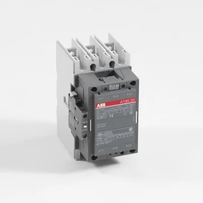
1SFL497062R7011 ABB: A 3-phase Contactor suitable for Rail way applications application. Operated with a wide voltage control voltage range 100-250 V, AC/DC
Minimum Order Quantity
1 piece
Customs Tariff Number
85364900
Replacement Product ID (NEW)
1SFL467062R1322
Data Sheet, Technical Information
1SBC100192C0206
Instructions and Manuals
Contactors A145, A185, A210, A260, A300
Dimension Diagram
53540923-7
Product Net Width
111.5 mm
Product Net Depth / Length
160 mm
Product Net Height
196 mm
Product Net Weight
2.9 kg
Number of Main Contacts NO
3
Number of Main Contacts NC
0
Number of Auxiliary Contacts NO
1
Number of Auxiliary Contacts NC
1
Number of Poles
3P
Standards
IEC/EN 60947-1, IEC/EN 60947-4-1, UL 60947-4-1, CSA C22.2 No. 60947-4-1, IEC 60077-1 (applicable parts), IEC 60077-2 (applicable parts), EN 50155 (applicable parts), TR CU 001/2011, IEC 61373, For compliance confirmation on applicable parts based on your application and combination, please consult your ABB sales representatives.
Rated Operational Voltage
Main Circuit 690 V
Rated Frequency (f)
Main Circuit 50 / 60 Hz
Conventional Free-air Thermal Current (Ith)
acc. to IEC 60947-4-1, Open Contactors Θ = 40 °C 275 A
Rated Operational Current AC-1 (Ie)
(1000 V) 40 °C 200 A | (1000 V) 55 °C 200 A | (1000 V) 70 °C 180 A | (690 V) 40 °C 275 A | (690 V) 55 °C 250 A | (690 V) 70 °C 180 A
Rated Operational Current AC-3 (Ie)
(415 V) 55 °C 185 A | (440 V) 55 °C 185 A | (500 V) 55 °C 170 A | (690 V) 55 °C 170 A | (1000 V) 55 °C 95 A | (380 / 400 V) 55 °C 185 A | (220 / 230 / 240 V) 55 °C 185
Rated Operational Current DC-1 (Ie)
(110 V) 2 Poles in Series, 40 °C 275 A | (220 V) 3 Poles in Series, 40 °C 275 A
Rated Operational Current DC-3 (Ie)
(110 V) 2 Poles in Series, 40 °C 275 A | (220 V) 3 Poles in Series, 40 °C 275 A
Rated Operational Current DC-5 (Ie)
(110 V) 2 Poles in Series, 40 °C 275 A | (220 V) 3 Poles in Series, 40 °C 275 A
Rated Operational Power AC-3 (Pe)
(415 V) 90 kW | (440 V) 90 kW | (500 V) 110 kW | (690 V) 132 kW | (1000 V) 132 kW | (380 / 400 V) 90 kW | (220 / 230 / 240 V) 55 kW
Rated Breaking Capacity AC-3
8 x Ie AC-3
Rated Making Capacity AC-3
10 x Ie AC-3
Short-Circuit Protective Devices
gG Type Fuses 160 A
Maximum Breaking Capacity
cos phi=0.45 (cos phi=0.35 for Ie > 100 A) at 440 V 2000 A | cos phi=0.45 (cos phi=0.35 for Ie > 100 A) at 690 V 1600 A
Rated Insulation Voltage (Ui)
acc. to IEC 60947-4-1 and VDE 0110 (Gr. C) 1000 V | acc. to UL/CSA 600 V
Rated Impulse Withstand Voltage (Uimp)
Main Circuit 8 kV
Maximum Electrical Switching Frequency
(AC-1) 300 cycles per hour | (AC-2 / AC-4) 150 cycles per hour | (AC-3) 300 cycles per hour
Mechanical Durability
5 million
Maximum Mechanical Switching Frequency
300 cycles per hour
Coil Operating Limits
(acc. to IEC 60947-4-1) 0.85 x Uc Min. ... 1.1 x Uc Max. (at θ ≤ 70 °C)
Rated Control Circuit Voltage (Uc)
50 Hz 100 ... 250 V | 60 Hz 100 ... 250 V | DC Operation 100 ... 250 V
Coil Consumption
Holding at Max. Rated Control Circuit Voltage 50 Hz 12 V·A | Holding at Max. Rated Control Circuit Voltage 60 Hz 12 V·A | Holding at Max. Rated Control Circuit Voltage DC 2 W | Pull-in at Max. Rated Control Circuit Voltage 50 Hz 430 V·A | Pull-in at Max. Rated Control Circuit Voltage 60 Hz 430 V·A | Pull-in at Max. Rated Control Circuit Voltage DC 500 W
Power Loss
at Rated Operating Conditions per Pole 8 W
Operate Time
Between Coil De-energization and NC Contact Closing 40 ... 50 ms | Between Coil De-energization and NO Contact Opening 43 ... 53 ms | Between Coil Energization and NC Contact Opening 45 ... 85 ms | Between Coil Energization and NO Contact Closing 50 ... 90 ms
Connecting Capacity Main Circuit
Bar 24 mm² | Rigid Al-Cable 25 ... 150 mm² | Rigid Cu-Cable 6 ... 185 mm²
Connecting Capacity Auxiliary Circuit
Flexible with Ferrule 1x 0.75 ... 2.5 mm² | Flexible with Insulated Ferrule 2x 0.75 ... 2.5 mm² | Flexible 1x0.75 ... 2.5 mm² | Solid 2 x 1 ... 4 mm² | Stranded 2 x 1 .... 4 mm²
Connecting Capacity
Bar 24 mm² | Rigid Al-Cable 25 ... 150 mm² | Rigid Cu-Cable 6 ... 185 mm²
Degree of Protection
acc. to IEC 60529, IEC 60947-1, EN 60529 Coil Terminals IP20 | acc. to IEC 60529, IEC 60947-1, EN 60529 Main Terminals IP00
Connecting Terminals (delivered in open position) Main Poles
Flat type c/w screws and bolts
Tightening Torque
Main Circuit 18 N·m
Terminal Type
Ring-Tongue Terminals
Product Name
Block Contactor
Maximum Operating Voltage UL/CSA
Main Circuit 600 V
General Use Rating UL/CSA
(600 V AC) 250 A
Horsepower Rating UL/CSA
(200 V AC) Three Phase 50 hp | (208 V AC) Three Phase 50 hp | (220 ... 240 V AC) Three Phase 60 hp | (440 ... 480 V AC) Three Phase 125 hp | (550 ... 600 V AC) Three Phase 150 hp
Full Load Amps Motor Use
(440 ... 480 V AC) Three Phase 156 A | (550 ... 600 V AC) Three Phase 144 A
Ambient Air Temperature
Close to Contactor Fitted with Thermal O/L Relay (0.85 ... 1.1 Uc) -25 ... 50 °C | Close to Contactor without Thermal O/L Relay (0.85 ... 1.1 Uc) -40 ... 70 °C | Close to Contactor for Storage -40 ... 70 °C
Maximum Operating Altitude Permissible
Without Derating 3000 m
Resistance to Shock acc. to IEC 60068-2-27
Shock Direction: A 5 g | Shock Direction: B1 5 g | Shock Direction: B2 5 g | Shock Direction: C1 5 g | Shock Direction: C2 5 g
RoHS Information
CE Declaration of Conformity - Contactor - A(F)95...A(F)300, AM110...AM300, UA95...UA110, (T)AE95....(T)AE110
RoHS Status
Following EU Directive 2011/65/EU
WEEE B2C / B2B
Business To Business
WEEE Category
5. Small Equipment (No External Dimension More Than 50 cm)
ABS Certificate
ABS Certificate, Contactor, AF400...AF2050 (Sweden)
BV Certificate
13409/C0 BV
CB Certificate
SE-69479
CQC Certificate
CQC Certificate, Contactor, AF145, AF185, AF145B...RT, AF185B...RT, Made in Sweden
Declaration of Conformity - CCC
CCC Declaration of Conformity, Contactor, AF145, AF185, AF145B...RT, AF185B...RT, Made in Sweden
Declaration of Conformity - CE
CE Declaration of Conformity - Contactor - A(F)95...A(F)300, AM110...AM300, UA95...UA110, (T)AE95....(T)AE110
EAC Certificate
9AKK107046A8618
GL Certificate
GL_20261-04HH
LOVAG Certificate
SE-0115106
LR Certificate
LR_04-00015-E1
RINA Certificate
ELE060313XG/002
RMRS Certificate
RMRS_12-03683-315
Package Level 1 Units
box 1 piece
Package Level 1 Width
178 mm
Package Level 1 Depth / Length
232 mm
Package Level 1 Height
167 mm
Package Level 1 Gross Weight
3.5 kg
Package Level 1 EAN
7320500260302
Object Classification Code
Q
ETIM 7
EC000066 - Power contactor, AC switching
ETIM 8
EC000066 - Power contactor, AC switching
ETIM 9
EC000066 - Power contactor, AC switching
eClass
V11.0 : 27371003
UNSPSC
39121529
IDEA Granular Category Code (IGCC)
4755 >> Contactors
E-Number (Norway)
4115323
The 1SFL497062R7011 features a wide control voltage range of 100–250 V AC/DC, enabling flexible integration with existing control systems and reducing stocking requirements across projects. This translates to lower total cost of ownership and faster commissioning in rail and industrial drives, while improving uptime through consistent coil performance and reduced field adjustments. With 3 main NO contacts plus 1 auxiliary NO and 1 auxiliary NC, it delivers straightforward interlocking and simplified wiring for safer, more predictable start-up sequences in heavy machinery and rolling stock. Rated for main circuit voltages up to 690 V and 50/60 Hz, the device supports high-power switching with minimized arc energy and improved life; this is critical in traction drives and conveyor systems where reliability matters most. The device’s insulation, IP ratings, and safe operating area align with IEC/UL standards, reducing compliance risk and enabling drop-in replacements in compatible panels. Mechanical durability of up to 5 million cycles provides long-term performance in frequent switching scenarios, while a compact footprint and clear terminalization support quick installation and maintenance. The wiring connections support a broad range of conductor sizes (24 mm² bars, 25–150 mm² rigid Al, 6–185 mm² rigid Cu) and standard ring-tongue terminals, ensuring robust, vibration-resistant connections in vehicle and plant environments. In practice, this translates to predictable maintenance windows, reduced wiring errors, and improved overall system uptime for rail signaling, drives, and automation cabinets.
Get a Quick Quote for a ABB 1SFL497062R7011
Chat with us on WhatsApp - fast responses guaranteed
Need to speak with someone? We'll call you back within 2 hours during business hours
Interested in ABB 1SFL497062R7011?
Enquire Now
FAQs
Plan for a three-pole device with 111.5 mm width, 160 mm depth, and 196 mm height. Use flat main terminals with bolts and ensure a tightening torque of 18 N·m for reliable connections. Coil terminals are IP20 and main terminals IP00, enabling safe installation in standard enclosures with appropriate protection against vibration and dust.
Rated operational current AC-3 at 690 V and 55 °C is 170 A, with a rated power around 132 kW for higher voltage configurations. The contactor supports a maximum breaking capacity defined as cos phi 0.45, and is designed for up to 300 cycles per hour in AC-1, with reduced frequency for AC-3/AC-4. These specs suit high-demand motor starting in rail drive systems.
Yes. It carries CE declarations of conformity and UL/CSA approvals for various voltage and insulation configurations. Additional certifications include CCC, CQC, EN 50155 applicability, and EN 60947-4-1 compliance. This broad certification support reduces regulatory risk in multinational rail and industrial deployments and ensures compatibility with enterprise-approved procurement processes.
The contactor offers up to 5 million mechanical cycles, minimizing replacement frequency in repetitive switching applications. Coil consumption remains efficient, with 50 Hz holding at max rated voltage around 12 VA per coil and pull-in around 430–500 VA, reducing standby power draw. The robust construction and standardized connection methods simplify inspection, diagnostics, and preventive maintenance planning.
Ideal for traction drives, rail signaling, and auxiliary control circuits in rolling stock and rail substations. Its 3P arrangement with 3 NO main contacts and 1 NO + 1 NC auxiliary contact supports interlocking and safety functions. The device's wide coil voltage range and 690 V main circuit rating ensure reliable operation in varied supply conditions typical of rail systems.