ABB 1SFL497062R7211 Contactor - IEC 60947-4-1
Part Number: 1SFL497062R7211
Quick Summary
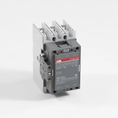
ABB 1SFL497062R7211 Contactor is a three-pole, DC-coil controlled switch engineered for railway and demanding automation tasks. Engineers often face reliability and compatibility challenges when switching high-power loads from a DC control source across varying voltages and harsh environments. This device complies with IEC/EN 60947-1 and 60947-4-1, UL 60947-4-1, and EN 50155, with CE and related approvals to support mobility and rail projects. Its compact 2.9 kg package, wide 20–60 V DC coil range, and robust IP ratings simplify panel design while delivering predictable switching performance in rail and industrial applications. In addition to core electrical specs, ABB offers familiar terminal styles and documented replacement parts to streamline maintenance and lifecycle planning.
Product Information
Extended Description
1SFL497062R7211 ABB: A 3-phase Contactor suitable for Rail way applications application. Operated with a wide voltage control voltage range 20-60 V, DC
Minimum Order Quantity
1 piece
Customs Tariff Number
85364900
Replacement Product ID (NEW)
1SFL467062R1122
Data Sheet, Technical Information
1SBC100192C0206
Instructions and Manuals
Contactors A145, A185, A210, A260, A300
Dimension Diagram
53540923-7
Product Net Width
111.5 mm
Product Net Depth / Length
160 mm
Product Net Height
196 mm
Product Net Weight
2.9 kg
Number of Main Contacts NO
3
Number of Main Contacts NC
0
Number of Auxiliary Contacts NO
1
Number of Auxiliary Contacts NC
1
Number of Poles
3P
Standards
IEC/EN 60947-1, IEC/EN 60947-4-1, UL 60947-4-1, CSA C22.2 No. 60947-4-1, IEC 60077-1 (applicable parts), IEC 60077-2 (applicable parts), EN 50155 (applicable parts), TR CU 001/2011, IEC 61373, For compliance confirmation on applicable parts based on your application and combination, please consult your ABB sales representatives.
Rated Operational Voltage
Main Circuit 690 V
Rated Frequency (f)
Main Circuit 50 / 60 Hz
Conventional Free-air Thermal Current (Ith)
acc. to IEC 60947-4-1, Open Contactors Θ = 40 °C 275 A
Rated Operational Current AC-1 (Ie)
(1000 V) 40 °C 200 A | (1000 V) 55 °C 200 A | (1000 V) 70 °C 180 A | (690 V) 40 °C 275 A | (690 V) 55 °C 250 A | (690 V) 70 °C 180 A
Rated Operational Current AC-3 (Ie)
(415 V) 55 °C 185 A | (440 V) 55 °C 185 A | (500 V) 55 °C 170 A | (690 V) 55 °C 170 A | (1000 V) 55 °C 95 A | (380 / 400 V) 55 °C 185 A | (220 / 230 / 240 V) 55 °C 185
Rated Operational Current DC-1 (Ie)
(110 V) 2 Poles in Series, 40 °C 275 A | (220 V) 3 Poles in Series, 40 °C 275 A
Rated Operational Current DC-3 (Ie)
(110 V) 2 Poles in Series, 40 °C 275 A | (220 V) 3 Poles in Series, 40 °C 275 A
Rated Operational Current DC-5 (Ie)
(110 V) 2 Poles in Series, 40 °C 275 A | (220 V) 3 Poles in Series, 40 °C 275 A
Rated Operational Power AC-3 (Pe)
(415 V) 90 kW | (440 V) 90 kW | (500 V) 110 kW | (690 V) 132 kW | (1000 V) 132 kW | (380 / 400 V) 90 kW | (220 / 230 / 240 V) 55 kW
Rated Breaking Capacity AC-3
8 x Ie AC-3
Rated Making Capacity AC-3
10 x Ie AC-3
Short-Circuit Protective Devices
gG Type Fuses 160 A
Maximum Breaking Capacity
cos phi=0.45 (cos phi=0.35 for Ie > 100 A) at 440 V 2000 A | cos phi=0.45 (cos phi=0.35 for Ie > 100 A) at 690 V 1600 A
Rated Insulation Voltage (Ui)
acc. to IEC 60947-4-1 and VDE 0110 (Gr. C) 1000 V | acc. to UL/CSA 600 V
Rated Impulse Withstand Voltage (Uimp)
Main Circuit 8 kV
Maximum Electrical Switching Frequency
(AC-1) 300 cycles per hour | (AC-2 / AC-4) 150 cycles per hour | (AC-3) 300 cycles per hour
Mechanical Durability
5 million
Maximum Mechanical Switching Frequency
300 cycles per hour
Coil Operating Limits
(acc. to IEC 60947-4-1) 0.85 x Uc Min. ... 1.1 x Uc Max. (at θ ≤ 70 °C)
Rated Control Circuit Voltage (Uc)
DC Operation 20 ... 60 V
Coil Consumption
Holding at Max. Rated Control Circuit Voltage 50 Hz 12 V·A | Holding at Max. Rated Control Circuit Voltage 60 Hz 12 V·A | Holding at Max. Rated Control Circuit Voltage DC 2 W | Pull-in at Max. Rated Control Circuit Voltage 50 Hz 430 V·A | Pull-in at Max. Rated Control Circuit Voltage 60 Hz 430 V·A | Pull-in at Max. Rated Control Circuit Voltage DC 500 W
Power Loss
at Rated Operating Conditions per Pole 8 W
Operate Time
Between Coil De-energization and NC Contact Closing 40 ... 50 ms | Between Coil De-energization and NO Contact Opening 43 ... 53 ms | Between Coil Energization and NC Contact Opening 45 ... 85 ms | Between Coil Energization and NO Contact Closing 50 ... 90 ms
Connecting Capacity Main Circuit
Bar 24 mm² | Rigid Al-Cable 25 ... 150 mm² | Rigid Cu-Cable 6 ... 185 mm²
Connecting Capacity Auxiliary Circuit
Flexible with Ferrule 2x 0.75 ... 2.5 mm² | Flexible with Insulated Ferrule 1x 0.75 ... 2.5 mm² | Flexible 2x0.75 ... 2.5 mm² | Solid 2 x 1 ... 4 mm² | Stranded 2 x 1 .... 4 mm²
Connecting Capacity
Bar 24 mm² | Rigid Al-Cable 25 ... 150 mm² | Rigid Cu-Cable 6 ... 185 mm²
Degree of Protection
acc. to IEC 60529, IEC 60947-1, EN 60529 Coil Terminals IP20 | acc. to IEC 60529, IEC 60947-1, EN 60529 Main Terminals IP00
Connecting Terminals (delivered in open position) Main Poles
Flat type c/w screws and bolts
Tightening Torque
Main Circuit 18 N·m
Terminal Type
Ring-Tongue Terminals
Product Name
Block Contactor
Maximum Operating Voltage UL/CSA
Main Circuit 600 V
General Use Rating UL/CSA
(600 V AC) 250 A
Horsepower Rating UL/CSA
(200 V AC) Three Phase 50 hp | (208 V AC) Three Phase 50 hp | (220 ... 240 V AC) Three Phase 60 hp | (440 ... 480 V AC) Three Phase 125 hp | (550 ... 600 V AC) Three Phase 150 hp
Full Load Amps Motor Use
(440 ... 480 V AC) Three Phase 156 A | (550 ... 600 V AC) Three Phase 144 A
Ambient Air Temperature
Close to Contactor Fitted with Thermal O/L Relay (0.85 ... 1.1 Uc) -25 ... 50 °C | Close to Contactor without Thermal O/L Relay (0.85 ... 1.1 Uc) -40 ... 70 °C | Close to Contactor for Storage -40 ... 70 °C
Maximum Operating Altitude Permissible
Without Derating 3000 m
Resistance to Shock acc. to IEC 60068-2-27
Shock Direction: A 5 g | Shock Direction: B1 5 g | Shock Direction: B2 5 g | Shock Direction: C1 5 g | Shock Direction: C2 5 g
RoHS Information
CE Declaration of Conformity - Contactor - A(F)95...A(F)300, AM110...AM300, UA95...UA110, (T)AE95....(T)AE110
RoHS Status
Following EU Directive 2011/65/EU
WEEE B2C / B2B
Business To Business
WEEE Category
5. Small Equipment (No External Dimension More Than 50 cm)
ABS Certificate
ABS Certificate, Contactor, AF400...AF2050 (Sweden)
BV Certificate
13409/C0 BV
CB Certificate
SE-69479
CQC Certificate
CQC Certificate, Contactor, AF145, AF185, AF145B...RT, AF185B...RT, Made in Sweden
Declaration of Conformity - CCC
CCC Declaration of Conformity, Contactor, AF145, AF185, AF145B...RT, AF185B...RT, Made in Sweden
Declaration of Conformity - CE
CE Declaration of Conformity - Contactor - A(F)95...A(F)300, AM110...AM300, UA95...UA110, (T)AE95....(T)AE110
EAC Certificate
9AKK107046A8618
GL Certificate
GL_20261-04HH
LOVAG Certificate
SE-0115106
LR Certificate
LR_04-00015-E1
RINA Certificate
ELE060313XG/002
RMRS Certificate
RMRS_12-03683-315
Package Level 1 Units
box 1 piece
Package Level 1 Width
178 mm
Package Level 1 Depth / Length
232 mm
Package Level 1 Height
167 mm
Package Level 1 Gross Weight
3.5 kg
Package Level 1 EAN
7320500260319
Object Classification Code
Q
ETIM 7
EC000066 - Power contactor, AC switching
ETIM 8
EC000066 - Power contactor, AC switching
ETIM 9
EC000066 - Power contactor, AC switching
eClass
V11.0 : 27371003
UNSPSC
39121529
IDEA Granular Category Code (IGCC)
4755 >> Contactors
Feature → Business Impact → Application: DC coil control 20–60 V reduces wiring complexity and enables direct integration with low-voltage control systems, cutting cabinet footprint and wiring costs in railway power distribution. Application: railway rolling stock, automated gates, and yard equipment. Feature → 3 main NO contacts with 1 auxiliary NO and 1 auxiliary NC → Simplified control logic and interlocking capability, reducing wiring and potential fault points in signaling and control circuits. Feature → Rated main circuit up to 690 V, with AC-3 current ratings up to 185 A (at 440–690 V) and 275 A (at 690 V, 40 °C) → Supports high-power motor control and load switching with reliable protection and short-circuit capability, improving line uptime. Feature → Coil consumption across hold and pull-in states (12 W DC hold, 430–500 W pull-in) → Optimized energy use during hold, enabling smaller power supplies and reduced heat in panels. Feature → Mechanical durability of 5 million operations and maximum mechanical switching frequency 300 cycles/hour → Long service life with predictable maintenance intervals, lowering total cost of ownership. Feature → IP20 coil terminals and IP00 main terminals → Streamlined installation with clear separation of coil and power sections, improving safety and serviceability. Feature → Connecting capacity for main and auxiliary circuits (bars, Al-Cable, Cu-Cable ranges) and tightening torque 18 N·m → Reliable, vibration-tolerant connections suitable for rail environments and harsh industrial settings. Feature → Comprehensive standards coverage (IEC/EN 60947-1, 60947-4-1, UL/CSA, EN 50155) → Compliance assurance across markets, reducing certification cycles and enabling multi-region deployments. Industry insight: The combination of a robust railway-oriented IEC standard footprint with ABB’s proven coil performance supports both new builds and retrofit projects, delivering improved uptime and a lower spare-part burden for maintenance teams.
Get a Quick Quote for a ABB 1SFL497062R7211
Chat with us on WhatsApp - fast responses guaranteed
Need to speak with someone? We'll call you back within 2 hours during business hours
Interested in ABB 1SFL497062R7211?
Enquire Now
FAQs
The device is a three-pole block contactor with flat-type main terminals supplied in the open position. Main terminals accept 24 mm² bar, rigid Al-Cable 25–150 mm², and rigid Cu-Cable 6–185 mm². Auxiliary circuits accept flexible, ferrule, and solid conductors in the 0.75–4 mm² range. Tightening torque for the main circuit is 18 N·m, ensuring solid, vibration-resistant connections suitable for rail environments.
Rated Operational Current AC-3 at 690 V is 275 A at 40 °C, 250 A at 55 °C, and 180 A at 70 °C. For AC-1 operation at 690 V, the device supports up to 275 A at 40 °C, 250 A at 55 °C, and 180 A at 70 °C. Coil controls are DC within 20–60 V, with 12 W holding power per coil and up to 500 W pull-in power depending on the drive characteristics.
Yes. It is designed for railway applications and adheres to EN 50155, IEC 60947-4-1, UL 60947-4-1, and related standards. It also has applicable CT and CCC/CE declarations, making it appropriate for mobile equipment and transit systems while meeting stringent reliability and environmental requirements.
The unit carries IEC/EN 60947-1, IEC/EN 60947-4-1, UL 60947-4-1, CSA C22.2 No. 60947-4-1, EN 50155 (applicable parts), TR CU 001/2011, IEC 61373 and multiple product declarations (CE, CCC, GL, BV, LR, RINA, RMRS, ABS). This broad certification footprint supports global deployment and regulatory compliance across industries.
The contactor offers a mechanical durability rating of 5 million operations and a maximum mechanical switching frequency of 300 cycles/hour, which translates to lower maintenance and longer replacement intervals in high-cycle environments. A replacement product ID is 1SFL467062R1122, aiding lifecycle planning and stock optimization, while the coil and connection design supports reliable long-term operation in rail and industrial settings.