ABB 1SFL517001R7011 Contactor - CE Certified 690V
Part Number: 1SFL517001R7011
Quick Summary
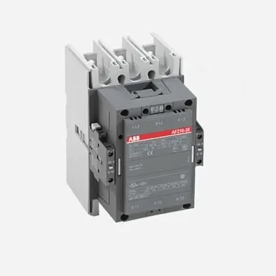
ABB 1SFL517001R7011 Contactor is designed for reliable motor starting and power distribution in industrial automation environments. Operators and maintenance teams often struggle with control voltage drift and wiring complexity across mixed AC/DC systems. This 3-pole block contactor delivers a wide control voltage range of 100–250 V and handles main circuits up to 690 V, backed by CE compliance and UL/CSA listings for global acceptance. With 3 NO main contacts and 1 NO plus 1 NC auxiliary contact, it provides integrated control signaling for compact panels and streamlined wiring. Built for OEMs and service teams, it supports efficient installation, predictable performance, and lower lifecycle costs in demanding applications.
Product Information
Extended Description
1SFL517001R7011 ABB: A 3-phase Contactor suitable for various applications such as Motor starting, Isolation, By-pass and Distribution application up to max 690 V. Operated with wide control voltage range 100-250 V, AC/DC
Country of Origin
Sweden (SE)
Lead Time
56 day
Made To Order
No
Product Sales Status
Inactive
Quote Only
No
Warranty Return
Product under warranty must be returned
Minimum Order Quantity
1 piece
Customs Tariff Number
85364900
Replacement Product ID (NEW)
1SFL527002R1311
Data Sheet, Technical Information
1SBC100192C0206
Instructions and Manuals
Contactors A145, A185, A210, A260, A300
Dimension Diagram
53540930-2
Product Net Width
140 mm
Product Net Depth / Length
180.5 mm
Product Net Height
227 mm
Product Net Weight
5.05 kg
Number of Main Contacts NO
3
Number of Main Contacts NC
0
Number of Auxiliary Contacts NO
1
Number of Auxiliary Contacts NC
1
Number of Poles
3P
Rated Operational Voltage
Main Circuit 690 V
Rated Frequency (f)
Main Circuit 50 / 60 Hz
Conventional Free-air Thermal Current (Ith)
acc. to IEC 60947-4-1, Open Contactors Θ = 40 °C 350 A
Rated Operational Current AC-1 (Ie)
(690 V) 40 °C 350 A | (690 V) 55 °C 300 A | (690 V) 70 °C 240 A
Rated Operational Current AC-3 (Ie)
(415 V) 55 °C 210 A | (440 V) 55 °C 210 A | (500 V) 55 °C 210 A | (690 V) 55 °C 210 A | (380 / 400 V) 55 °C 210 A | (220 / 230 / 240 V) 55 °C 210
Rated Operational Current DC-1 (Ie)
(110 V) 2 Poles in Series, 40 °C 350 A | (220 V) 3 Poles in Series, 40 °C 350 A
Rated Operational Current DC-3 (Ie)
(110 V) 2 Poles in Series, 40 °C 350 A | (220 V) 3 Poles in Series, 40 °C 350 A
Rated Operational Current DC-5 (Ie)
(110 V) 2 Poles in Series, 40 °C 350 A | (220 V) 3 Poles in Series, 40 °C 350 A
Rated Operational Power AC-3 (Pe)
(415 V) 110 kW | (440 V) 110 kW | (500 V) 132 kW | (690 V) 160 kW | (380 / 400 V) 110 kW | (220 / 230 / 240 V) 59 kW
Rated Breaking Capacity AC-3
8 x Ie AC-3
Rated Making Capacity AC-3
10 x Ie AC-3
Short-Circuit Protective Devices
gG Type Fuses 400 A
Rated Short-time Withstand Current Low Voltage (Icw)
at 40 °C Ambient Temp, in Free Air, from a Cold State 10 s 1700 A | at 40 °C Ambient Temp, in Free Air, from a Cold State 15 min 400 A | at 40 °C Ambient Temp, in Free Air, from a Cold State 1 min 1000 A | at 40 °C Ambient Temp, in Free Air, from a Cold State 1 s 2500 A | at 40 °C Ambient Temp, in Free Air, from a Cold State 30 s 1200 A
Maximum Breaking Capacity
cos phi=0.45 (cos phi=0.35 for Ie > 100 A) at 440 V 2200 A | cos phi=0.45 (cos phi=0.35 for Ie > 100 A) at 690 V 2000 A
Rated Insulation Voltage (Ui)
acc. to IEC 60947-4-1 and VDE 0110 (Gr. C) 1000 V | acc. to UL/CSA 600 V
Rated Impulse Withstand Voltage (Uimp)
Main Circuit 8 kV
Maximum Electrical Switching Frequency
(AC-1) 300 cycles per hour | (AC-2 / AC-4) 150 cycles per hour | (AC-3) 300 cycles per hour
Mechanical Durability
5 million
Maximum Mechanical Switching Frequency
300 cycles per hour
Coil Operating Limits
(acc. to IEC 60947-4-1) 0.85 x Uc Min. ... 1.1 x Uc Max. (at θ ≤ 70 °C)
Rated Control Circuit Voltage (Uc)
50 Hz 100 ... 250 V | 60 Hz 100 ... 250 V | DC Operation 100 ... 250 V
Coil Consumption
Holding at Max. Rated Control Circuit Voltage 50 Hz 10 V·A | Holding at Max. Rated Control Circuit Voltage 60 Hz 10 V·A | Holding at Max. Rated Control Circuit Voltage DC 2 W | Pull-in at Max. Rated Control Circuit Voltage 50 Hz 470 V·A | Pull-in at Max. Rated Control Circuit Voltage 60 Hz 470 V·A | Pull-in at Max. Rated Control Circuit Voltage DC 520 W
Power Loss
at Rated Operating Conditions per Pole 9 W
Operate Time
Between Coil De-energization and NC Contact Closing 40 .... 50 ms | Between Coil De-energization and NO Contact Opening 43 ... 53 ms | Between Coil Energization and NC Contact Opening 45 ... 85 ms | Between Coil Energization and NO Contact Closing 50 ... 90 ms
Connecting Capacity Main Circuit
Bar 32 mm² | Rigid Al-Cable 2 x 95 ... 120 mm² | Rigid Cu-Cable 16 ... 240 mm²
Connecting Capacity Auxiliary Circuit
Flexible with Ferrule 1x 0.75 ... 2.5 mm² | Flexible with Insulated Ferrule 1x 0.75 ... 2.5 mm² | Flexible 2x0.75 ... 2.5 mm² | Solid 2 x 1 ... 4 mm² | Stranded 2 x 1 .... 4 mm²
Connecting Capacity
Bar 32 mm² | Rigid Al-Cable 2 x 95 ... 120 mm² | Rigid Cu-Cable 16 ... 240 mm²
Degree of Protection
acc. to IEC 60529, IEC 60947-1, EN 60529 Coil Terminals IP20 | acc. to IEC 60529, IEC 60947-1, EN 60529 Main Terminals IP00
Tightening Torque
Main Circuit 18 N·m
Terminal Type
Main Circuit: Bars
Product Name
Block Contactor
Maximum Operating Voltage UL/CSA
Main Circuit 600 V
General Use Rating UL/CSA
(600 V AC) 300 A
Horsepower Rating UL/CSA
(200 V AC) Three Phase 60 hp | (208 V AC) Three Phase 60 hp | (220 ... 240 V AC) Three Phase 75 hp | (440 ... 480 V AC) Three Phase 150 hp | (550 ... 600 V AC) Three Phase 200 hp
Full Load Amps Motor Use
(440 ... 480 V AC) Three Phase 180 A | (550 ... 600 V AC) Three Phase 192 A
Ambient Air Temperature
Close to Contactor Fitted with Thermal O/L Relay (0.85 ... 1.1 Uc) -25 ... 50 °C | Close to Contactor without Thermal O/L Relay (0.85 ... 1.1 Uc) -40 ... 70 °C | Close to Contactor for Storage -40 ... 70 °C
Maximum Operating Altitude Permissible
Without Derating 3000 m
Resistance to Shock acc. to IEC 60068-2-27
Shock Direction: A 5 g | Shock Direction: B1 5 g | Shock Direction: B2 5 g | Shock Direction: C1 5 g | Shock Direction: C2 5 g
RoHS Information
CE Declaration of Conformity - Contactor - A(F)95...A(F)300, AM110...AM300, UA95...UA110, (T)AE95....(T)AE110
RoHS Status
Following EU Directive 2011/65/EU
WEEE B2C / B2B
Business To Business
WEEE Category
5. Small Equipment (No External Dimension More Than 50 cm)
ABS Certificate
ABS Certificate, Contactor, AF400...AF2050 (Sweden)
BV Certificate
BV Certificate, Contactor, AF400 ... AF2850
CB Certificate
SEMKO_SE-69491A1
CCS Certificate
CCS Certificate, Contactor, AF116 to AF2850 (Sweden)
CQC Certificate
CQC Certificate, Contactor, AF210, AF210B…RT, AF260, AF260B…RT, AF300, AF300B…RT, Made in Sweden
Declaration of Conformity - CCC
CCC Declaration of Conformity, Contactor, AF210, AF210B…RT, AF260, AF260B…RT, AF300, AF300B…RT, Made in Sweden
Declaration of Conformity - CE
CE Declaration of Conformity - Contactor - A(F)95...A(F)300, AM110...AM300, UA95...UA110, (T)AE95....(T)AE110
DNV GL Certificate
DNV Certificate, Contactor, AF400...AF2850
EAC Certificate
9AKK107046A8618
GL Certificate
GL_20262-04HH
LOVAG Certificate
SE-0115198
LR Certificate
Lloyds register Certificate, Contactor, AF400...AF2850
RINA Certificate
RINA Certificate, AF95, AF110, AF145, AF185, AF210, AF260, AF300, AF400, AF460, AF580, AF750, AF1250, AF1350, AF1650, AF2050, AF2650, AF116, AF140, AF146, AF190, AF205, AF265, AF305, AF370
RMRS Certificate
RMRS_12-03683-315
Package Level 1 Units
box 1 piece
Package Level 1 Width
203 mm
Package Level 1 Depth / Length
245 mm
Package Level 1 Height
188 mm
Package Level 1 Gross Weight
5.75 kg
Package Level 1 EAN
7320500220276
Object Classification Code
Q
ETIM 7
EC000066 - Power contactor, AC switching
ETIM 8
EC000066 - Power contactor, AC switching
ETIM 9
EC000066 - Power contactor, AC switching
eClass
V11.0 : 27371003
UNSPSC
39121529
IDEA Granular Category Code (IGCC)
4755 >> Contactors
E-Number (Finland)
3709247
E-Number (Norway)
4115275
E-Number (Sweden)
3228306
Feature: Three-pole main contacts (3 NO) with one NO auxiliary and one NC auxiliary. Impact: Enables direct motor switching and integrated control signaling, reducing external relays and panel space. Application: Suitable for three-phase motors in conveyors, pumps, and fans across manufacturing lines. Feature: Wide coil control voltage of 100–250 V AC/DC with 50/60 Hz compatibility. Impact: Offers flexible control sourcing and simpler retrofits when PLC outputs vary by site. Application: Ideal for new builds and retrofits in OEM equipment and process automation. Feature: Rated operational currents across AC-1 and AC-3 ranges and DC-1/3/5 variants (up to 350 A for main circuit at 690 V, depending on temperature). Impact: Ensures reliable motor starting and protection for high-inertia loads, reducing nuisance trips. Application: Suitable for pump packs, conveyors, and fans where motor loads reach high startup currents. Feature: High breaking capacity and short-time withstand: 8 x Ie AC-3; Icw up to 2500 A for short transients. Impact: Delivers robust interrupt performance and improved safety margins in fault conditions. Application: Critical for heavy-duty industrial drives and process lines. Feature: Mechanical durability of 5 million cycles. Impact: Extends maintenance intervals and reduces total cost of ownership. Application: Ideal for high-cycle applications like packaging lines and material handling. Feature: Flexible connection options: Bar 32 mm² main; rigid Al-Cu cables up to 16–240 mm². Impact: Simplifies wiring during panel fabrication and field retrofits. Application: Supports standard busbar mounting and versatile cable routing. Feature: Protection and environmental resilience: IP20 coil terminals; IP00 main terminals; operating temperature -25 to 50°C (with thermal relays) and -40 to 70°C (without). Impact: Ensures safe operation in typical industrial environments and broad temperature ranges. Application: Suitable for factory floors, assemblies, and controlled enclosures.
Get a Quick Quote for a ABB 1SFL517001R7011
Chat with us on WhatsApp - fast responses guaranteed
Need to speak with someone? We'll call you back within 2 hours during business hours
Interested in ABB 1SFL517001R7011?
Enquire Now
FAQs
Install on a rigid panel using the 32 mm² main busbar or suitable rigid cables. Tighten main terminals to 18 N·m and ensure proper alignment of the auxiliary contacts. Verify coil supply is within 100–250 V (50/60 Hz) and confirm IP20 coil terminals for safe operation. Always follow enclosure clearance and protection guidelines.
The coil accepts 100–250 V across AC or DC, with 50/60 Hz operation. This wide range supports flexible control sourcing from PLCs and VFDs, and facilitates retrofits where supply conditions vary while maintaining fast, reliable coil actuation.
Yes. The device is rated for main circuits up to 690 V and delivers AC-3 performance suitable for motor starting with high inrush currents. For 690 V operation at 55 °C, the Ie is 210 A, with higher ratings at other temperatures, providing dependable starting for medium-to-large motors.
It carries CE conformity and UL/CSA listings, with additional approvals such as LR, BV, DNV GL, RINA, ABS, and CG verification across multiple global certification programs, ensuring broad regulatory acceptance for international deployment.
Plan for periodic inspections of contact wear and insulation integrity. The unit offers about 5 million mechanical cycles, aids in reducing maintenance frequency, and carries a warranty framework requiring return of warranty-covered products. For reduced risk, monitor operating temperature and ensure clean, dust-free mounting in ventilated enclosures.