ABB 1SFL517001R7211 Block Contactor - CE Declaration of Conformity
Part Number: 1SFL517001R7211
Quick Summary
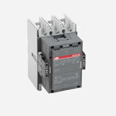
Block Contactor ABB 1SFL517001R7211 enables motor starting in DC control applications. Engineers often contend with wiring complexity, mounting footprint, and ensuring reliable control across variable voltages. This device carries CE conformity with UL/CSA approvals and multiple third‑party certificates (ABS, BV, GL), providing regulatory confidence across international projects. By combining a wide 20–60 V DC control range with a robust 690 V main circuit and three poles, it supports scalable automation while minimizing cabinet size and wiring complexity. The compact 140 mm width and 5.05 kg weight simplify panel layouts, and the device’s reinforced insulation and established lifecycle performance translate into lower maintenance and a lower total cost of ownership.
Product Information
Extended Description
1SFL517001R7211 ABB: A 3-phase Contactor suitable for various applications such as Motor starting, Isolation, By-pass and Distribution application up to max 690 V. Operated with wide control voltage range 20-60 V, DC
Minimum Order Quantity
1 piece
Customs Tariff Number
85364900
Replacement Product ID (NEW)
1SFL527002R1111
Data Sheet, Technical Information
1SBC100192C0206
Instructions and Manuals
Contactors A145, A185, A210, A260, A300
Dimension Diagram
53540930-2
Product Net Width
140 mm
Product Net Depth / Length
180.5 mm
Product Net Height
227 mm
Product Net Weight
5.05 kg
Number of Main Contacts NO
3
Number of Main Contacts NC
0
Number of Auxiliary Contacts NO
1
Number of Auxiliary Contacts NC
1
Number of Poles
3P
Rated Operational Voltage
Main Circuit 690 V
Rated Frequency (f)
Main Circuit 50 / 60 Hz
Conventional Free-air Thermal Current (Ith)
acc. to IEC 60947-4-1, Open Contactors Θ = 40 °C 350 A
Rated Operational Current AC-1 (Ie)
(690 V) 40 °C 350 A | (690 V) 55 °C 300 A | (690 V) 70 °C 240 A
Rated Operational Current AC-3 (Ie)
(415 V) 55 °C 210 A | (440 V) 55 °C 210 A | (500 V) 55 °C 210 A | (690 V) 55 °C 210 A | (380 / 400 V) 55 °C 210 A | (220 / 230 / 240 V) 55 °C 210
Rated Operational Current DC-1 (Ie)
(110 V) 2 Poles in Series, 40 °C 350 A | (220 V) 3 Poles in Series, 40 °C 350 A
Rated Operational Current DC-3 (Ie)
(110 V) 2 Poles in Series, 40 °C 350 A | (220 V) 3 Poles in Series, 40 °C 350 A
Rated Operational Current DC-5 (Ie)
(110 V) 2 Poles in Series, 40 °C 350 A | (220 V) 3 Poles in Series, 40 °C 350 A
Rated Operational Power AC-3 (Pe)
(415 V) 110 kW | (440 V) 110 kW | (500 V) 132 kW | (690 V) 160 kW | (380 / 400 V) 110 kW | (220 / 230 / 240 V) 59 kW
Rated Breaking Capacity AC-3
8 x Ie AC-3
Rated Making Capacity AC-3
10 x Ie AC-3
Short-Circuit Protective Devices
gG Type Fuses 400 A
Rated Short-time Withstand Current Low Voltage (Icw)
at 40 °C Ambient Temp, in Free Air, from a Cold State 10 s 1700 A | at 40 °C Ambient Temp, in Free Air, from a Cold State 15 min 400 A | at 40 °C Ambient Temp, in Free Air, from a Cold State 1 min 1000 A | at 40 °C Ambient Temp, in Free Air, from a Cold State 1 s 2500 A | at 40 °C Ambient Temp, in Free Air, from a Cold State 30 s 1200 A
Maximum Breaking Capacity
cos phi=0.45 (cos phi=0.35 for Ie > 100 A) at 440 V 2200 A | cos phi=0.45 (cos phi=0.35 for Ie > 100 A) at 690 V 2000 A
Rated Insulation Voltage (Ui)
acc. to IEC 60947-4-1 and VDE 0110 (Gr. C) 1000 V | acc. to UL/CSA 600 V
Rated Impulse Withstand Voltage (Uimp)
Main Circuit 8 kV
Maximum Electrical Switching Frequency
(AC-1) 300 cycles per hour | (AC-2 / AC-4) 150 cycles per hour | (AC-3) 300 cycles per hour
Mechanical Durability
5 million
Maximum Mechanical Switching Frequency
300 cycles per hour
Coil Operating Limits
(acc. to IEC 60947-4-1) 0.85 x Uc Min. ... 1.1 x Uc Max. (at θ ≤ 70 °C)
Rated Control Circuit Voltage (Uc)
DC Operation 20 ... 60 V
Coil Consumption
Holding at Max. Rated Control Circuit Voltage 50 Hz 10 V·A | Holding at Max. Rated Control Circuit Voltage 60 Hz 10 V·A | Holding at Max. Rated Control Circuit Voltage DC 2 W | Pull-in at Max. Rated Control Circuit Voltage 50 Hz 470 V·A | Pull-in at Max. Rated Control Circuit Voltage 60 Hz 470 V·A | Pull-in at Max. Rated Control Circuit Voltage DC 520 W
Power Loss
at Rated Operating Conditions per Pole 9 W
Operate Time
Between Coil De-energization and NC Contact Closing 40 .... 50 ms | Between Coil De-energization and NO Contact Opening 43 ... 53 ms | Between Coil Energization and NC Contact Opening 45 ... 85 ms | Between Coil Energization and NO Contact Closing 50 ... 90 ms
Connecting Capacity Main Circuit
Bar 32 mm² | Rigid Al-Cable 2 x 95 ... 120 mm² | Rigid Cu-Cable 16 ... 240 mm²
Connecting Capacity Auxiliary Circuit
Flexible with Ferrule 1x 0.75 ... 2.5 mm² | Flexible with Insulated Ferrule 2x 0.75 ... 2.5 mm² | Flexible 2x0.75 ... 2.5 mm² | Solid 2 x 1 ... 4 mm² | Stranded 2 x 1 .... 4 mm²
Connecting Capacity
Bar 32 mm² | Rigid Al-Cable 2 x 95 ... 120 mm² | Rigid Cu-Cable 16 ... 240 mm²
Degree of Protection
acc. to IEC 60529, IEC 60947-1, EN 60529 Coil Terminals IP20 | acc. to IEC 60529, IEC 60947-1, EN 60529 Main Terminals IP00
Tightening Torque
Main Circuit 18 N·m
Terminal Type
Main Circuit: Bars
Product Name
Block Contactor
Maximum Operating Voltage UL/CSA
Main Circuit 600 V
General Use Rating UL/CSA
(600 V AC) 300 A
Horsepower Rating UL/CSA
(200 V AC) Three Phase 60 hp | (208 V AC) Three Phase 60 hp | (220 ... 240 V AC) Three Phase 75 hp | (440 ... 480 V AC) Three Phase 150 hp | (550 ... 600 V AC) Three Phase 200 hp
Full Load Amps Motor Use
(440 ... 480 V AC) Three Phase 180 A | (550 ... 600 V AC) Three Phase 192 A
Ambient Air Temperature
Close to Contactor Fitted with Thermal O/L Relay (0.85 ... 1.1 Uc) -25 ... 50 °C | Close to Contactor without Thermal O/L Relay (0.85 ... 1.1 Uc) -40 ... 70 °C | Close to Contactor for Storage -40 ... 70 °C
Maximum Operating Altitude Permissible
Without Derating 3000 m
Resistance to Shock acc. to IEC 60068-2-27
Shock Direction: A 5 g | Shock Direction: B1 5 g | Shock Direction: B2 5 g | Shock Direction: C1 5 g | Shock Direction: C2 5 g
RoHS Information
CE Declaration of Conformity - Contactor - A(F)95...A(F)300, AM110...AM300, UA95...UA110, (T)AE95....(T)AE110
RoHS Status
Following EU Directive 2011/65/EU
WEEE B2C / B2B
Business To Business
WEEE Category
5. Small Equipment (No External Dimension More Than 50 cm)
ABS Certificate
ABS Certificate, Contactor, AF400...AF2050 (Sweden)
BV Certificate
BV Certificate, Contactor, AF400 ... AF2850
CB Certificate
SEMKO_SE-69491A1
CCS Certificate
CCS Certificate, Contactor, AF116 to AF2850 (Sweden)
CQC Certificate
CQC Certificate, Contactor, AF210, AF210B…RT, AF260, AF260B…RT, AF300, AF300B…RT, Made in Sweden
Declaration of Conformity - CCC
CCC Declaration of Conformity, Contactor, AF210, AF210B…RT, AF260, AF260B…RT, AF300, AF300B…RT, Made in Sweden
Declaration of Conformity - CE
CE Declaration of Conformity - Contactor - A(F)95...A(F)300, AM110...AM300, UA95...UA110, (T)AE95....(T)AE110
DNV GL Certificate
DNV Certificate, Contactor, AF400...AF2850
EAC Certificate
9AKK107046A8618
GL Certificate
GL_20262-04HH
LOVAG Certificate
SE-0115198
LR Certificate
Lloyds register Certificate, Contactor, AF400...AF2850
RINA Certificate
RINA Certificate, AF95, AF110, AF145, AF185, AF210, AF260, AF300, AF400, AF460, AF580, AF750, AF1250, AF1350, AF1650, AF2050, AF2650, AF116, AF140, AF146, AF190, AF205, AF265, AF305, AF370
RMRS Certificate
RMRS_12-03683-315
TÜV Certificate
MHM-EST-7.70017788e
Package Level 1 Units
box 1 piece
Package Level 1 Width
203 mm
Package Level 1 Depth / Length
245 mm
Package Level 1 Height
188 mm
Package Level 1 Gross Weight
5.75 kg
Package Level 1 EAN
7320500220252
Object Classification Code
Q
ETIM 7
EC000066 - Power contactor, AC switching
ETIM 8
EC000066 - Power contactor, AC switching
ETIM 9
EC000066 - Power contactor, AC switching
eClass
V11.0 : 27371003
UNSPSC
39121529
IDEA Granular Category Code (IGCC)
4755 >> Contactors
E-Number (Norway)
4115277
E-Number (Sweden)
3228302
Coil range and energy efficiency enable direct interfacing with standard PLC outputs, reducing wiring and control hardware while delivering reliable switching for DC drives. The 20–60 V DC control voltage supports flexible control schemes across varying supply conditions, improving overall system resilience and reducing integration time in new or retrofit projects. The rated main circuit up to 690 V and 3P configuration provide ample headroom for motor starting and distribution in demanding industrial environments, delivering predictable performance and lower risk of nuisance trips. Mechanical durability of 5 million cycles translates to longer service life and reduced maintenance intervals in continuous process lines. The IP20 coil terminals and IP00 main terminals simplify installation in standard enclosures, while an 18 N·m tightening torque ensures secure, vibration‑resistant connections. Connecting capacity allows Bar 32 mm² or Cu/Al cables up to 120 mm², streamlining cabinet layouts and minimizing termination steps. Compliance with RoHS and multiple international certificates reduces sourcing risk and accelerates time‑to‑production for global deployments. Overall, the device supports lower total cost of ownership through robust performance, easier installation, and durable operation across temperature and altitude variations.
Get a Quick Quote for a ABB 1SFL517001R7211
Chat with us on WhatsApp - fast responses guaranteed
Need to speak with someone? We'll call you back within 2 hours during business hours
Interested in ABB 1SFL517001R7211?
Enquire Now
FAQs
Plan panel layout to accommodate Bar 32 mm² main circuit connections or rigid Al-Cu cables up to 120 mm². Use the recommended tightening torque of 18 N·m for main terminals, and ensure coil terminals are protected with IP20 enclosure. Ensure ambient temperature remains within -25 to 50 °C when protected and up to -40 to 70 °C without thermal O/L relay. Maintain clearance for heat dissipation and service access.
Main circuit rated up to 690 V with 50/60 Hz operation. Auxiliary contacts include 1 NO and 1 NC. Rated operational current AC-3 up to 210 A at 55 °C, and up to 210 A at 690 V. Coil control voltage is 20–60 V DC with coil consumption of 2 W holding (DC) and 470–520 V·A pull-in values. Short-circuit protection uses gG fuses up to 400 A, and insulation voltage is 1000 V.
Yes. The device is designed for motor starting, isolation, bypass, and distribution in DC control schemes. With three NO main contacts and a 3P configuration, it provides robust switching for motor loads, while the 690 V main circuit rating supports common industrial drive voltages. High breaking capacity and fast operate times help minimize electrical stress and wear on downstream components.
The ABB 1SFL517001R7211 carries CE conformity and UL/CSA general use approvals, with extensive third‑party certifications including ABS, BV, GL, RINA, LR, DNV GL, RMRS, CQC, and TÜV. RoHS compliance is confirmed, and WEEE categorization is B2B. This broad approvals footprint helps ensure regulatory compliance across global manufacturing sites and simplifies supplier qualification.
With a mechanical durability rating of 5 million cycles and a compact, robust form factor, maintenance intervals are extended and downtime reduced. The wide coil control range minimizes control interface complexity, while high current ratings and solid insulation reduce the risk of nuisance trips and insulation failure. Overall, expect lower lifecycle costs, faster installation, and improved asset availability in conveyors, presses, and motor-driven lines.