ABB 1SFL517001R7222 Block Contactor - 350A 690V
Part Number: 1SFL517001R7222
Quick Summary
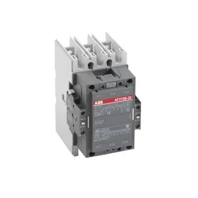
The ABB 1SFL517001R7222 block contactor is designed for motor starting and control in 3-phase systems up to 690 V. Engineers often face downtime from coil mismatches and undersized current ratings, which this device addresses with a wide DC coil range of 20–60 V and high Ie values. Certified for CE, UL/CSA, and TÜV, the unit also carries RoHS compliance and robust environmental ratings to minimize risk across global operations. Its versatility translates into simpler inventories, faster panel assembly, and predictable performance in drives, pumps, and conveyors.
Product Information
Extended Description
1SFL517001R7222 ABB: A 3-phase Contactor suitable for various applications such as Motor starting, Isolation, By-pass and Distribution application up to max 690 V. Operated with wide control voltage range 20-60 V, DC
Minimum Order Quantity
1 piece
Customs Tariff Number
85364900
Replacement Product ID (NEW)
1SFL527002R1122
Data Sheet, Technical Information
1SBC100192C0206
Instructions and Manuals
Contactors A145, A185, A210, A260, A300
Dimension Diagram
53540930-2
Product Net Width
140 mm
Product Net Depth / Length
180.5 mm
Product Net Height
227 mm
Product Net Weight
5.1 kg
Number of Main Contacts NO
3
Number of Main Contacts NC
0
Number of Auxiliary Contacts NO
2
Number of Auxiliary Contacts NC
2
Number of Poles
3P
Rated Operational Voltage
Main Circuit 690 V
Rated Frequency (f)
Main Circuit 50 / 60 Hz
Conventional Free-air Thermal Current (Ith)
acc. to IEC 60947-4-1, Open Contactors Θ = 40 °C 350 A
Rated Operational Current AC-1 (Ie)
(690 V) 40 °C 350 A | (690 V) 55 °C 300 A | (690 V) 70 °C 240 A
Rated Operational Current AC-3 (Ie)
(415 V) 55 °C 210 A | (440 V) 55 °C 210 A | (500 V) 55 °C 210 A | (690 V) 55 °C 210 A | (380 / 400 V) 55 °C 210 A | (220 / 230 / 240 V) 55 °C 210
Rated Operational Current DC-1 (Ie)
(110 V) 2 Poles in Series, 40 °C 350 A | (220 V) 3 Poles in Series, 40 °C 350 A
Rated Operational Current DC-3 (Ie)
(110 V) 2 Poles in Series, 40 °C 350 A | (220 V) 3 Poles in Series, 40 °C 350 A
Rated Operational Current DC-5 (Ie)
(110 V) 2 Poles in Series, 40 °C 350 A | (220 V) 3 Poles in Series, 40 °C 350 A
Rated Operational Power AC-3 (Pe)
(415 V) 110 kW | (440 V) 110 kW | (500 V) 132 kW | (690 V) 160 kW | (380 / 400 V) 110 kW | (220 / 230 / 240 V) 59 kW
Rated Breaking Capacity AC-3
8 x Ie AC-3
Rated Making Capacity AC-3
10 x Ie AC-3
Short-Circuit Protective Devices
gG Type Fuses 400 A
Rated Short-time Withstand Current Low Voltage (Icw)
at 40 °C Ambient Temp, in Free Air, from a Cold State 10 s 1700 A | at 40 °C Ambient Temp, in Free Air, from a Cold State 15 min 400 A | at 40 °C Ambient Temp, in Free Air, from a Cold State 1 min 1000 A | at 40 °C Ambient Temp, in Free Air, from a Cold State 1 s 2500 A | at 40 °C Ambient Temp, in Free Air, from a Cold State 30 s 1200 A
Maximum Breaking Capacity
cos phi=0.45 (cos phi=0.35 for Ie > 100 A) at 440 V 2200 A | cos phi=0.45 (cos phi=0.35 for Ie > 100 A) at 690 V 2000 A
Rated Insulation Voltage (Ui)
acc. to IEC 60947-4-1 and VDE 0110 (Gr. C) 1000 V | acc. to UL/CSA 600 V
Rated Impulse Withstand Voltage (Uimp)
Main Circuit 8 kV
Maximum Electrical Switching Frequency
(AC-1) 300 cycles per hour | (AC-2 / AC-4) 150 cycles per hour | (AC-3) 300 cycles per hour
Mechanical Durability
5 million
Maximum Mechanical Switching Frequency
300 cycles per hour
Coil Operating Limits
(acc. to IEC 60947-4-1) 0.85 x Uc Min. ... 1.1 x Uc Max. (at θ ≤ 70 °C)
Rated Control Circuit Voltage (Uc)
DC Operation 20 ... 60 V
Coil Consumption
Holding at Max. Rated Control Circuit Voltage 50 Hz 10 V·A | Holding at Max. Rated Control Circuit Voltage 60 Hz 10 V·A | Holding at Max. Rated Control Circuit Voltage DC 2 W | Pull-in at Max. Rated Control Circuit Voltage 50 Hz 470 V·A | Pull-in at Max. Rated Control Circuit Voltage 60 Hz 470 V·A | Pull-in at Max. Rated Control Circuit Voltage DC 520 W
Power Loss
at Rated Operating Conditions per Pole 9 W
Operate Time
Between Coil De-energization and NC Contact Closing 40 .... 50 ms | Between Coil De-energization and NO Contact Opening 43 ... 53 ms | Between Coil Energization and NC Contact Opening 45 ... 85 ms | Between Coil Energization and NO Contact Closing 50 ... 90 ms
Connecting Capacity Main Circuit
Bar 32 mm² | Rigid Al-Cable 120 ... 240 mm² | Rigid Cu-Cable 16 ... 240 mm²
Connecting Capacity Auxiliary Circuit
Flexible with Ferrule 1x 0.75 ... 2.5 mm² | Flexible with Insulated Ferrule 2x 0.75 ... 2.5 mm² | Flexible 2x0.75 ... 2.5 mm² | Solid 1 x 1 ... 4 mm² | Stranded 2 x 1 .... 4 mm²
Connecting Capacity
Bar 32 mm² | Rigid Al-Cable 120 ... 240 mm² | Rigid Cu-Cable 16 ... 240 mm²
Degree of Protection
acc. to IEC 60529, IEC 60947-1, EN 60529 Coil Terminals IP20 | acc. to IEC 60529, IEC 60947-1, EN 60529 Main Terminals IP00
Tightening Torque
Main Circuit 18 N·m
Terminal Type
Main Circuit: Bars
Product Name
Block Contactor
Maximum Operating Voltage UL/CSA
Main Circuit 600 V
General Use Rating UL/CSA
(600 V AC) 300 A
Horsepower Rating UL/CSA
(200 V AC) Three Phase 60 hp | (208 V AC) Three Phase 60 hp | (220 ... 240 V AC) Three Phase 75 hp | (440 ... 480 V AC) Three Phase 150 hp | (550 ... 600 V AC) Three Phase 200 hp
Full Load Amps Motor Use
(440 ... 480 V AC) Three Phase 180 A | (550 ... 600 V AC) Three Phase 192 A
Ambient Air Temperature
Close to Contactor Fitted with Thermal O/L Relay (0.85 ... 1.1 Uc) -25 ... 50 °C | Close to Contactor without Thermal O/L Relay (0.85 ... 1.1 Uc) -40 ... 70 °C | Close to Contactor for Storage -40 ... 70 °C
Maximum Operating Altitude Permissible
Without Derating 3000 m
Resistance to Shock acc. to IEC 60068-2-27
Shock Direction: A 5 g | Shock Direction: B1 5 g | Shock Direction: B2 5 g | Shock Direction: C1 5 g | Shock Direction: C2 5 g
RoHS Information
CE Declaration of Conformity - Contactor - A(F)95...A(F)300, AM110...AM300, UA95...UA110, (T)AE95....(T)AE110
RoHS Status
Following EU Directive 2011/65/EU
WEEE B2C / B2B
Business To Business
WEEE Category
5. Small Equipment (No External Dimension More Than 50 cm)
ABS Certificate
ABS Certificate, Contactor, AF400...AF2050 (Sweden)
BV Certificate
BV Certificate, Contactor, AF400 ... AF2850
CB Certificate
SEMKO_SE-69491A1
CCS Certificate
CCS Certificate, Contactor, AF116 to AF2850 (Sweden)
CQC Certificate
CQC Certificate, Contactor, AF210, AF210B…RT, AF260, AF260B…RT, AF300, AF300B…RT, Made in Sweden
Declaration of Conformity - CCC
CCC Declaration of Conformity, Contactor, AF210, AF210B…RT, AF260, AF260B…RT, AF300, AF300B…RT, Made in Sweden
Declaration of Conformity - CE
CE Declaration of Conformity - Contactor - A(F)95...A(F)300, AM110...AM300, UA95...UA110, (T)AE95....(T)AE110
DNV GL Certificate
DNV Certificate, Contactor, AF400...AF2850
EAC Certificate
9AKK107046A8618
GL Certificate
GL_20262-04HH
LOVAG Certificate
SE-0115198
LR Certificate
Lloyds register Certificate, Contactor, AF400...AF2850
RINA Certificate
RINA Certificate, AF95, AF110, AF145, AF185, AF210, AF260, AF300, AF400, AF460, AF580, AF750, AF1250, AF1350, AF1650, AF2050, AF2650, AF116, AF140, AF146, AF190, AF205, AF265, AF305, AF370
RMRS Certificate
RMRS_12-03683-315
TÜV Certificate
MHM-EST-7.70017788e
Package Level 1 Units
box 1 piece
Package Level 1 Width
203 mm
Package Level 1 Depth / Length
245 mm
Package Level 1 Height
188 mm
Package Level 1 Gross Weight
5.8 kg
Package Level 1 EAN
7320500222805
Object Classification Code
Q
ETIM 7
EC000066 - Power contactor, AC switching
ETIM 8
EC000066 - Power contactor, AC switching
ETIM 9
EC000066 - Power contactor, AC switching
eClass
V11.0 : 27371003
UNSPSC
39121529
IDEA Granular Category Code (IGCC)
4755 >> Contactors
Coil voltage flexibility enables universal control from a single supply, reducing spare-part inventories and wiring errors during startup while supporting reliable operation in DC driving schemes and industrial automation panels. Application: motor starters and motor control circuits in conveyors, pumps, and fans benefit from streamlined wiring and reduced commissioning time. The main circuit is rated for up to 690 V with 3 NO main contacts and 2 NO auxiliary contacts, handling heavy motor loads with confidence; this translates to fewer contactor replacements and improved line continuity in packaging, materials handling, and process industries. With power loss kept to around 9 W per pole, holding and pull-in currents are optimized for energy efficiency and thermal stability in switchgear assemblies, supporting compliance with energy management goals. Durability is a standout feature with 5 million mechanical cycles, minimizing maintenance windows and service costs in continuous-process environments such as water treatment and HVAC systems. Installation and wiring are simplified by bar-type main terminals (32 mm²) and clear connection schemes for rigid Al/Cu cables (16–240 mm²); this speeds panel wiring and reduces risk of loose connections. The unit also features IP20 coil terminals and IP00 main terminals, plus a tightening torque of 18 N·m on the main circuit, ensuring reliable, vibration-tolerant operation in rugged industrial settings. RoHS compliance, CE/UL/CSA certifications, and TÜV attestations provide regulatory assurance for global deployments, while a compact footprint and standardized dimensioning support retrofit installations in legacy control panels.
Get a Quick Quote for a ABB 1SFL517001R7222
Chat with us on WhatsApp - fast responses guaranteed
Need to speak with someone? We'll call you back within 2 hours during business hours
Interested in ABB 1SFL517001R7222?
Enquire Now
FAQs
Begin by verifying coil voltage compatibility (DC 20–60 V) and identify the main circuit terminals. Connect the main circuit with 32 mm² bus bars or 16–240 mm² rigid Cu/Al cables per the product specification, and secure auxiliary contacts per the schematic. Tighten main terminals to 18 N·m and mount the unit in a suitable enclosure with IP20 coil protection. Verify wiring integrity and perform functional testing with no-load and loaded motor conditions.
Rated for main circuit operation up to 690 V with 50/60 Hz, the contactor provides AC-3 Ie up to 210 A at 690 V and DC-3 Ie up to 350 A for 110–220 V configurations. Short-circuit protection uses gG fuses up to 400 A. It supports 3 NO main contacts and 2 NO auxiliary contacts, with a maximum breaking capacity suitable for demanding motor switching tasks.
Yes. It carries CE declaration of conformity, UL/CSA general use ratings, and TÜV certification, along with RoHS compliance. These certifications support regulatory compliance for global deployments in manufacturing, packaging, and process industries, enabling safer panel integration and easier cross-border acceptance.
The device uses main circuit terminals designed for 32 mm² bars and rigid cables up to 240 mm², simplifying wiring and reducing assembly time. Its compact dimensions (width 140 mm, depth 180.5 mm, height 227 mm) and weight of about 5.1 kg ease mounting in crowded control panels. Coil terminals are IP20 protected, and the overall design aids reliable torqueing and vibration resistance.
With a mechanical durability rating of 5 million cycles and modular compatibility for both AC- and DC-driven applications, the contactor minimizes replacements and maintenance downtime. The wide coil voltage tolerance reduces spare-part variety, while the high current capability supports larger motor loads, delivering faster payback through reduced downtime, lower energy waste, and simplified spare-part inventories.