ABB 1SFL517062R6911 Block Contactor - IEC 60947-4-1
Part Number: 1SFL517062R6911
Quick Summary
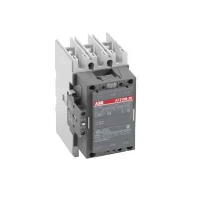
ABB 1SFL517062R6911 Block Contactor is a high‑capacity switching device designed for railway applications. Engineers frequently face challenges securing reliable control across wide coil voltage ranges while maintaining uptime in harsh environments. This 3‑pole, 3 NO main contact design also includes 1 NO and 1 NC auxiliary contacts, with a coil control voltage from 48 to 130 V and a main circuit rated up to 690 V, backed by robust certifications. By aligning with IEC/EN 60947‑4‑1 and UL/CSA requirements, it delivers consistent performance, simplifies compliance, and reduces spare‑part complexity. The combination of wide control voltage, durable mechanical life, and clear mounting/termination options supports streamlined automation projects and a lower total cost of ownership.
Product Information
Extended Description
1SFL517062R6911 ABB: A 3-phase Contactor suitable for Rail way applications application. Operated with a wide voltage control voltage range 48-130 V, AC/DC
Minimum Order Quantity
1 piece
Customs Tariff Number
85364900
Replacement Product ID (NEW)
1SFL527062R1222
Data Sheet, Technical Information
1SBC100192C0206
Instructions and Manuals
Contactors A145, A185, A210, A260, A300
Dimension Diagram
53540930-2
Product Net Width
140 mm
Product Net Depth / Length
180.5 mm
Product Net Height
227 mm
Product Net Weight
5.4 kg
Number of Main Contacts NO
3
Number of Main Contacts NC
0
Number of Auxiliary Contacts NO
1
Number of Auxiliary Contacts NC
1
Number of Poles
3P
Standards
IEC/EN 60947-1, IEC/EN 60947-4-1, UL 60947-4-1, CSA C22.2 No. 60947-4-1, IEC 60077-1 (applicable parts), IEC 60077-2 (applicable parts), EN 50155 (applicable parts), TR CU 001/2011, IEC 61373, For compliance confirmation on applicable parts based on your application and combination, please consult your ABB sales representatives.
Rated Operational Voltage
Main Circuit 690 V
Rated Frequency (f)
Main Circuit 50 / 60 Hz
Conventional Free-air Thermal Current (Ith)
acc. to IEC 60947-4-1, Open Contactors Θ = 40 °C 350 A
Rated Operational Current AC-1 (Ie)
(690 V) 40 °C 350 A | (690 V) 55 °C 300 A | (690 V) 70 °C 240 A
Rated Operational Current AC-3 (Ie)
(415 V) 55 °C 210 A | (440 V) 55 °C 210 A | (500 V) 55 °C 210 A | (690 V) 55 °C 210 A | (380 / 400 V) 55 °C 210 A | (220 / 230 / 240 V) 55 °C 210
Rated Operational Current DC-1 (Ie)
(110 V) 2 Poles in Series, 40 °C 350 A | (220 V) 3 Poles in Series, 40 °C 350 A
Rated Operational Current DC-3 (Ie)
(110 V) 2 Poles in Series, 40 °C 350 A | (220 V) 3 Poles in Series, 40 °C 350 A
Rated Operational Current DC-5 (Ie)
(110 V) 2 Poles in Series, 40 °C 350 A | (220 V) 3 Poles in Series, 40 °C 350 A
Rated Operational Power AC-3 (Pe)
(415 V) 110 kW | (440 V) 110 kW | (500 V) 132 kW | (690 V) 160 kW | (380 / 400 V) 110 kW | (220 / 230 / 240 V) 59 kW
Rated Breaking Capacity AC-3
8 x Ie AC-3
Rated Making Capacity AC-3
10 x Ie AC-3
Short-Circuit Protective Devices
gG Type Fuses 160 A
Maximum Breaking Capacity
cos phi=0.45 (cos phi=0.35 for Ie > 100 A) at 440 V 2200 A | cos phi=0.45 (cos phi=0.35 for Ie > 100 A) at 690 V 2000 A
Rated Insulation Voltage (Ui)
acc. to IEC 60947-4-1 and VDE 0110 (Gr. C) 1000 V | acc. to UL/CSA 600 V
Rated Impulse Withstand Voltage (Uimp)
Main Circuit 8 kV
Maximum Electrical Switching Frequency
(AC-1) 300 cycles per hour | (AC-2 / AC-4) 150 cycles per hour | (AC-3) 300 cycles per hour
Mechanical Durability
5 million
Maximum Mechanical Switching Frequency
300 cycles per hour
Coil Operating Limits
(acc. to IEC 60947-4-1) 0.85 x Uc Min. ... 1.1 x Uc Max. (at θ ≤ 70 °C)
Rated Control Circuit Voltage (Uc)
50 Hz 48 ... 130 V | 60 Hz 48 ... 130 V | DC Operation 48 ... 130 V
Coil Consumption
Holding at Max. Rated Control Circuit Voltage 50 Hz 10 V·A | Holding at Max. Rated Control Circuit Voltage 60 Hz 10 V·A | Holding at Max. Rated Control Circuit Voltage DC 2 W | Pull-in at Max. Rated Control Circuit Voltage 50 Hz 470 V·A | Pull-in at Max. Rated Control Circuit Voltage 60 Hz 470 V·A | Pull-in at Max. Rated Control Circuit Voltage DC 520 W
Power Loss
at Rated Operating Conditions per Pole 9 W
Operate Time
Between Coil De-energization and NC Contact Closing 40 ... 50 ms | Between Coil De-energization and NO Contact Opening 43 ... 53 ms | Between Coil Energization and NC Contact Opening 45 ... 85 ms | Between Coil Energization and NO Contact Closing 50 ... 90 ms
Connecting Capacity Main Circuit
Bar 32 mm² | Rigid Al-Cable 2 x 95 ... 120 mm² | Rigid Cu-Cable 16 ... 240 mm²
Connecting Capacity Auxiliary Circuit
Flexible with Ferrule 2x 0.75 ... 2.5 mm² | Flexible with Insulated Ferrule 2x 0.75 ... 2.5 mm² | Flexible 2x0.75 ... 2.5 mm² | Solid 2 x 1 ... 4 mm² | Stranded 1 x 1 .... 4 mm²
Connecting Capacity
Bar 32 mm² | Rigid Al-Cable 2 x 95 ... 120 mm² | Rigid Cu-Cable 16 ... 240 mm²
Degree of Protection
acc. to IEC 60529, IEC 60947-1, EN 60529 Coil Terminals IP20 | acc. to IEC 60529, IEC 60947-1, EN 60529 Main Terminals IP00
Connecting Terminals (delivered in open position) Main Poles
Flat type c/w screws and bolts
Tightening Torque
Main Circuit 18 N·m
Terminal Type
Ring-Tongue Terminals
Product Name
Block Contactor
Maximum Operating Voltage UL/CSA
Main Circuit 600 V
General Use Rating UL/CSA
(600 V AC) 300 A
Horsepower Rating UL/CSA
(200 V AC) Three Phase 60 hp | (208 V AC) Three Phase 60 hp | (220 ... 240 V AC) Three Phase 75 hp | (440 ... 480 V AC) Three Phase 150 hp | (550 ... 600 V AC) Three Phase 200 hp
Full Load Amps Motor Use
(440 ... 480 V AC) Three Phase 180 A | (550 ... 600 V AC) Three Phase 192 A
Ambient Air Temperature
Close to Contactor Fitted with Thermal O/L Relay (0.85 ... 1.1 Uc) -25 ... 50 °C | Close to Contactor without Thermal O/L Relay (0.85 ... 1.1 Uc) -40 ... 70 °C | Close to Contactor for Storage -40 ... 70 °C
Maximum Operating Altitude Permissible
Without Derating 3000 m
Resistance to Shock acc. to IEC 60068-2-27
Shock Direction: A 5 g | Shock Direction: B1 5 g | Shock Direction: B2 5 g | Shock Direction: C1 5 g | Shock Direction: C2 5 g
RoHS Information
CE Declaration of Conformity - Contactor - A(F)95...A(F)300, AM110...AM300, UA95...UA110, (T)AE95....(T)AE110
RoHS Status
Following EU Directive 2011/65/EU
WEEE B2C / B2B
Business To Business
WEEE Category
5. Small Equipment (No External Dimension More Than 50 cm)
ABS Certificate
ABS Certificate, Contactor, AF400...AF2050 (Sweden)
BV Certificate
13409/C0 BV
CB Certificate
SE-69491
CQC Certificate
CQC Certificate, Contactor, AF210, AF210B…RT, AF260, AF260B…RT, AF300, AF300B…RT, Made in Sweden
Declaration of Conformity - CCC
CCC Declaration of Conformity, Contactor, AF210, AF210B…RT, AF260, AF260B…RT, AF300, AF300B…RT, Made in Sweden
Declaration of Conformity - CE
CE Declaration of Conformity - Contactor - A(F)95...A(F)300, AM110...AM300, UA95...UA110, (T)AE95....(T)AE110
EAC Certificate
9AKK107046A8618
GL Certificate
GL_20262-04HH
LOVAG Certificate
SE-0115198
LR Certificate
LR_04-00015-E1
RINA Certificate
ELE060313XG/002
RMRS Certificate
RMRS_12-03683-315
Package Level 1 Units
box 1 piece
Package Level 1 Width
203 mm
Package Level 1 Depth / Length
245 mm
Package Level 1 Height
188 mm
Package Level 1 Gross Weight
6.1 kg
Package Level 1 EAN
7320500260326
Object Classification Code
Q
ETIM 7
EC000066 - Power contactor, AC switching
ETIM 8
EC000066 - Power contactor, AC switching
ETIM 9
EC000066 - Power contactor, AC switching
eClass
V11.0 : 27371003
UNSPSC
39121529
IDEA Granular Category Code (IGCC)
4755 >> Contactors
Feature → Business Impact → Application: The module is a 3P block contactor with 3 main NO contacts and 1 auxiliary NO plus 1 auxiliary NC, enabling compact motor control with extended fault‑tolerance and simplified diagnostics, improving maintenance planning and reducing downtime in trackside or yard automation. Feature → Business Impact → Application: Coil operating limits of 0.85 x Uc to 1.1 x Uc accommodate ambient temperature variations up to 70 °C, enabling reliable actuation in outdoor environments and under load swings typical in rail applications. Feature → Business Impact → Application: Coil range 48–130 V AC/DC offers flexibility for mixed voltage controls, reducing stock variety and installation complexity while supporting retrofits and standardization across multiple lines. Feature → Business Impact → Application: Rated main circuit 690 V and AC‑3 current up to 210 A (55 °C) ensure high‑efficiency switching for motors and pumps, cutting energy losses and enabling predictable performance in heavy‑duty drives. Feature → Business Impact → Application: Connection capacity for main circuit accommodates Bar 32 mm², rigid Al/Cu cables up to 120 mm², and flexible conductors, delivering solid, field‑friendly wiring with fast termination and reliable torque. Feature → Business Impact → Application: Mechanical durability rated at 5 million cycles supports long life in demanding rolling stock duty cycles, reducing replacement intervals and total maintenance costs. Feature → Business Impact → Application: Certifications and declarations (CE, UL/CSA, RoHS, CCC, EAC, GL, BV, ABS, and others) provide compliance confidence for global deployments and supplier audits, reducing risk in regulated environments. Feature → Business Impact → Application: Dimensioned to fit standard IEC panel layouts and rail industry enclosures, the product simplifies cabinet design and improves installation speed in automation projects.
Get a Quick Quote for a ABB 1SFL517062R6911
Chat with us on WhatsApp - fast responses guaranteed
Need to speak with someone? We'll call you back within 2 hours during business hours
Interested in ABB 1SFL517062R6911?
Enquire Now
FAQs
The contactor supports Bar 32 mm² main conductors and rigid Cu/Al cables from 16 to 240 mm², providing ample headroom for typical rail drive and auxiliary circuits. Its UL/CSA and CE certifications simplify integration with standard protection devices, while the 3 NO main contacts and 1 NO/1 NC auxiliary contact enable straightforward wiring of motor starters, contact protection, and signaling in safety circuits.
For AC-3 duty at 690 V, the device provides up to 210 A at 55 °C (and similar values at other voltages listed in the datasheet). It also supports DC operation with two/three poles in series up to 350 A, depending on voltage, and shows a rated power capacity around 110–160 kW depending on the line voltage. These ratings make it suitable for high‑power door actuators, conveyors, and traction components.
The product carries CE, UL/CSA, CB, CCC, EAC, ABS, BV, GL, LR, RINA, RMRS, and RoHS declarations, among others. It complies with IEC/EN 60947‑4‑1 and related standards, with additional regional certifications enabling global deployment in rail and industrial automation projects. Please consult ABB for confirmation on part‑wise applicability to specific configurations.
Main circuit terminals are rated IP00, and coil terminals are IP20, requiring careful enclosure protection in field installations. The tightening torque for main circuits is 18 N·m, and mounting should accommodate 3P configurations with flat main terminals and ring‑tongue connectors. Use appropriate circuit protection (gG fuses up to 160 A) and ensure temperature ratings meet ambient‑temperature operating ranges (−25 to 50 °C with a thermal relay or −40 to 70 °C without).
With a mechanical durability of up to 5 million cycles and low coil consumption—2 W hold and up to 470 W pull‑in—the device minimizes maintenance cycles and energy draw during standby. The wide voltage range and modular auxiliary contacts simplify diagnostics and spare‑parts planning, contributing to reduced downtime costs and lower ownership cost over its life in railway automation and industrial control systems.