ABB 1SFL517062R7211 Block Contactor - IEC 60947-4-1 compliant
Part Number: 1SFL517062R7211
Quick Summary
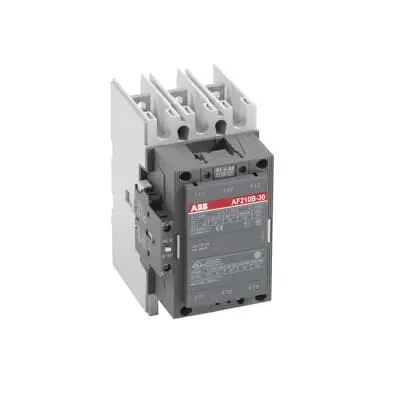
ABB 1SFL517062R7211 Block Contactor provides robust DC-driven switching for rail applications, delivering reliable control of three-phase motors in transit systems. Engineers frequently struggle with harmonizing a wide coil voltage range, panel space limitations, and complex certification requirements across rail networks. This ABB model carries CE Declaration of Conformity, UL/CSA General Use ratings, and GL/BV style certifications for enhanced compliance and risk reduction. Its compact footprint (140 mm W x 180.5 mm D x 227 mm H) and a weight of 5.4 kg support easier installation and maintenance in demanding environments. By combining a wide 20–60 V DC coil with high‑voltage main switching and versatile connections, it reduces inventory, accelerates commissioning, and improves overall system reliability.
Product Information
Extended Description
1SFL517062R7211 ABB: A 3-phase Contactor suitable for Rail way applications application. Operated with a wide voltage control voltage range 20-60 V, DC
Minimum Order Quantity
1 piece
Customs Tariff Number
85364900
Replacement Product ID (NEW)
1SFL527062R1122
Data Sheet, Technical Information
1SBC100192C0206
Instructions and Manuals
Contactors A145, A185, A210, A260, A300
Dimension Diagram
53540930-2
Product Net Width
140 mm
Product Net Depth / Length
180.5 mm
Product Net Height
227 mm
Product Net Weight
5.4 kg
Number of Main Contacts NO
3
Number of Main Contacts NC
0
Number of Auxiliary Contacts NO
1
Number of Auxiliary Contacts NC
1
Number of Poles
3P
Standards
IEC/EN 60947-1, IEC/EN 60947-4-1, UL 60947-4-1, CSA C22.2 No. 60947-4-1, IEC 60077-1 (applicable parts), IEC 60077-2 (applicable parts), EN 50155 (applicable parts), TR CU 001/2011, IEC 61373, For compliance confirmation on applicable parts based on your application and combination, please consult your ABB sales representatives.
Rated Operational Voltage
Main Circuit 690 V
Conventional Free-air Thermal Current (Ith)
acc. to IEC 60947-4-1, Open Contactors Θ = 40 °C 350 A
Rated Operational Current AC-1 (Ie)
(690 V) 40 °C 350 A | (690 V) 55 °C 300 A | (690 V) 70 °C 240 A
Rated Operational Current AC-3 (Ie)
(415 V) 55 °C 210 A | (440 V) 55 °C 210 A | (500 V) 55 °C 210 A | (690 V) 55 °C 210 A | (380 / 400 V) 55 °C 210 A | (220 / 230 / 240 V) 55 °C 210
Rated Operational Current DC-1 (Ie)
(110 V) 2 Poles in Series, 40 °C 350 A | (220 V) 3 Poles in Series, 40 °C 350 A
Rated Operational Current DC-3 (Ie)
(110 V) 2 Poles in Series, 40 °C 350 A | (220 V) 3 Poles in Series, 40 °C 350 A
Rated Operational Current DC-5 (Ie)
(110 V) 2 Poles in Series, 40 °C 350 A | (220 V) 3 Poles in Series, 40 °C 350 A
Rated Operational Power AC-3 (Pe)
(415 V) 110 kW | (440 V) 110 kW | (500 V) 132 kW | (690 V) 160 kW | (380 / 400 V) 110 kW | (220 / 230 / 240 V) 59 kW
Rated Breaking Capacity AC-3
8 x Ie AC-3
Rated Making Capacity AC-3
10 x Ie AC-3
Short-Circuit Protective Devices
gG Type Fuses 160 A
Maximum Breaking Capacity
cos phi=0.45 (cos phi=0.35 for Ie > 100 A) at 440 V 2200 A | cos phi=0.45 (cos phi=0.35 for Ie > 100 A) at 690 V 2000 A
Rated Insulation Voltage (Ui)
acc. to IEC 60947-4-1 and VDE 0110 (Gr. C) 1000 V | acc. to UL/CSA 600 V
Rated Impulse Withstand Voltage (Uimp)
Main Circuit 8 kV
Maximum Electrical Switching Frequency
(AC-1) 300 cycles per hour | (AC-2 / AC-4) 150 cycles per hour | (AC-3) 300 cycles per hour
Mechanical Durability
5 million
Maximum Mechanical Switching Frequency
300 cycles per hour
Coil Operating Limits
(acc. to IEC 60947-4-1) 0.85 x Uc Min. ... 1.1 x Uc Max. (at θ ≤ 70 °C)
Rated Control Circuit Voltage (Uc)
DC Operation 20 ... 60 V
Coil Consumption
Holding at Max. Rated Control Circuit Voltage 50 Hz 10 V·A | Holding at Max. Rated Control Circuit Voltage 60 Hz 10 V·A | Holding at Max. Rated Control Circuit Voltage DC 2 W | Pull-in at Max. Rated Control Circuit Voltage 50 Hz 470 V·A | Pull-in at Max. Rated Control Circuit Voltage 60 Hz 470 V·A | Pull-in at Max. Rated Control Circuit Voltage DC 520 W
Power Loss
at Rated Operating Conditions per Pole 9 W
Operate Time
Between Coil De-energization and NC Contact Closing 40 ... 50 ms | Between Coil De-energization and NO Contact Opening 43 ... 53 ms | Between Coil Energization and NC Contact Opening 45 ... 85 ms | Between Coil Energization and NO Contact Closing 50 ... 90 ms
Connecting Capacity Main Circuit
Bar 32 mm² | Rigid Al-Cable 2 x 95 ... 120 mm² | Rigid Cu-Cable 16 ... 240 mm²
Connecting Capacity Auxiliary Circuit
Flexible with Ferrule 2x 0.75 ... 2.5 mm² | Flexible with Insulated Ferrule 2x 0.75 ... 2.5 mm² | Flexible 2x0.75 ... 2.5 mm² | Solid 1 x 1 ... 4 mm² | Stranded 2 x 1 .... 4 mm²
Connecting Capacity
Bar 32 mm² | Rigid Al-Cable 120 ... 240 mm² | Rigid Cu-Cable 16 ... 240 mm²
Degree of Protection
acc. to IEC 60529, IEC 60947-1, EN 60529 Coil Terminals IP20 | acc. to IEC 60529, IEC 60947-1, EN 60529 Main Terminals IP00
Connecting Terminals (delivered in open position) Main Poles
Flat type c/w screws and bolts
Tightening Torque
Main Circuit 18 N·m
Terminal Type
Ring-Tongue Terminals
Product Name
Block Contactor
Maximum Operating Voltage UL/CSA
Main Circuit 600 V
General Use Rating UL/CSA
(600 V AC) 300 A
Horsepower Rating UL/CSA
(200 V AC) Three Phase 60 hp | (208 V AC) Three Phase 60 hp | (220 ... 240 V AC) Three Phase 75 hp | (440 ... 480 V AC) Three Phase 150 hp | (550 ... 600 V AC) Three Phase 200 hp
Full Load Amps Motor Use
(440 ... 480 V AC) Three Phase 180 A | (550 ... 600 V AC) Three Phase 192 A
Ambient Air Temperature
Close to Contactor Fitted with Thermal O/L Relay (0.85 ... 1.1 Uc) -25 ... 50 °C | Close to Contactor without Thermal O/L Relay (0.85 ... 1.1 Uc) -40 ... 70 °C | Close to Contactor for Storage -40 ... 70 °C
Maximum Operating Altitude Permissible
Without Derating 3000 m
Resistance to Shock acc. to IEC 60068-2-27
Shock Direction: A 5 g | Shock Direction: B1 5 g | Shock Direction: B2 5 g | Shock Direction: C1 5 g | Shock Direction: C2 5 g
RoHS Information
CE Declaration of Conformity - Contactor - A(F)95...A(F)300, AM110...AM300, UA95...UA110, (T)AE95....(T)AE110
RoHS Status
Following EU Directive 2011/65/EU
WEEE B2C / B2B
Business To Business
WEEE Category
5. Small Equipment (No External Dimension More Than 50 cm)
ABS Certificate
ABS Certificate, Contactor, AF400...AF2050 (Sweden)
BV Certificate
13409/C0 BV
CB Certificate
SE-69491
CQC Certificate
CQC Certificate, Contactor, AF210, AF210B…RT, AF260, AF260B…RT, AF300, AF300B…RT, Made in Sweden
Declaration of Conformity - CCC
CCC Declaration of Conformity, Contactor, AF210, AF210B…RT, AF260, AF260B…RT, AF300, AF300B…RT, Made in Sweden
Declaration of Conformity - CE
CE Declaration of Conformity - Contactor - A(F)95...A(F)300, AM110...AM300, UA95...UA110, (T)AE95....(T)AE110
EAC Certificate
9AKK107046A8618
GL Certificate
GL_20262-04HH
LOVAG Certificate
SE-0115198
LR Certificate
LR_04-00015-E1
RINA Certificate
ELE060313XG/002
RMRS Certificate
RMRS_12-03683-315
Package Level 1 Units
box 1 piece
Package Level 1 Width
203 mm
Package Level 1 Depth / Length
245 mm
Package Level 1 Height
188 mm
Package Level 1 Gross Weight
6.1 kg
Package Level 1 EAN
7320500260340
Object Classification Code
Q
ETIM 7
EC000066 - Power contactor, AC switching
ETIM 8
EC000066 - Power contactor, AC switching
ETIM 9
EC000066 - Power contactor, AC switching
eClass
V11.0 : 27371003
UNSPSC
39121529
IDEA Granular Category Code (IGCC)
4755 >> Contactors
Feature → Business Impact → Application: Coil operating range 20–60 V DC simplifies control logic and stock management, reducing spare parts variety while enabling faster installation and commissioning in rail control panels. Application: DC motor control in rail traction systems. Feature → 3 main NO contacts + 1 NO auxiliary + 1 NC auxiliary → Expanded control logic and interlocking capability, enabling safer sequencing and redundancy in door, braking, and auxiliary circuits. Application: Interlock schemes in train propulsion and auxiliary systems. Feature → Main circuit voltage up to 690 V and rated currents up to 210 A AC-3 at 690 V, plus DC-1/3/5 ratings → Suitable for high‑power switching with predictable performance, increasing uptime and reducing relay failures in traction drives. Application: Heavy-duty load switching in rail substations and rolling stock. Feature → gG protective devices supported (160 A) → Improves fault protection coordination with standard fusing and breaker schemes, lowering downstream protection costs. Application: System safety and compliance in electrical protection schemes. Feature → Dimensions 140 mm W × 180.5 mm D × 227 mm H and weight 5.4 kg with IP20 coil terminals/IP00 main terminals → Facilitates panel layout, reduces retrofit complexity, and ensures reliable terminal protection in rugged environments. Application: Panel integration in compact control cabinets. Feature → 32 mm² main circuit busbar compatibility and range of cable connections (120–240 mm² rigid copper/aluminum) → Wide wiring flexibility and faster termination, cutting installation time. Application: Field wiring in heavy-duty switchgear.
Get a Quick Quote for a ABB 1SFL517062R7211
Chat with us on WhatsApp - fast responses guaranteed
Need to speak with someone? We'll call you back within 2 hours during business hours
Interested in ABB 1SFL517062R7211?
Enquire Now
FAQs
The coil operates from 20 to 60 V DC, enabling compatibility with a wide range of control circuits and reducing the need for multiple coil variants in a single panel. This range supports flexible control logic for rail applications and simplifies stocking and sourcing across projects.
Yes. It meets UL/CSA General Use ratings for up to 600 V AC and 300 A in common configurations, alongside CE declarations and other global certifications. This broad certification footprint supports compliance in diverse regional projects and eases regulatory acceptance.
AC-3 ratings reach up to 210 A at 690 V (55 °C) and remain suitable across 415–690 V ranges. DC-3 ratings are 350 A when using two poles in series at 40 °C, enabling robust DC motor control for rail traction and related applications.
Main terminals support 32 mm² busbars and rigid Al/Cu cables from 16 to 240 mm², while coil terminals are IP20 protected with ring-tongue fits. This supports reliable, vibration-tolerant installation in compact control cabinets typical of rail environments.
Replacement product ID is 1SFL527062R1122. Access to the dimension diagram (53540930-2) and data sheet (1SBC100192C0206) is available through ABB’s technical collateral to support configuration, mounting, and maintenance planning.