ABB 1SFL537001R7211 Block Contactor - CE & UL/CSA Certified
Part Number: 1SFL537001R7211
Quick Summary
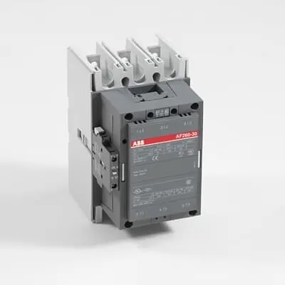
ABB 1SFL537001R7211 Block Contactor is a 3-pole DC-coil device for motor starting and isolation up to 690 V. In demanding installations, users often face coil voltage mismatches, mounting space constraints, and inconsistent control performance; this model provides a wide 20–60 V DC coil range and a compact footprint to help streamline panel design and commissioning. It carries CE conformity and UL/CSA listings, plus additional approvals such as BV, DNV GL, and RINA, supporting global compliance across projects. Designed for robust industrial environments, it integrates with standard 32 mm² main connections and reliable auxiliary wiring, delivering predictable operation and reduced maintenance time across motor control applications.
Product Information
Extended Description
1SFL537001R7211 ABB: A 3-phase Contactor suitable for various applications such as Motor starting, Isolation, By-pass and Distribution application up to max 690 V. Operated with wide control voltage range 60
Minimum Order Quantity
1 piece
Customs Tariff Number
85364900
Replacement Product ID (NEW)
1SFL547002R1111
Data Sheet, Technical Information
1SBC100192C0206
Instructions and Manuals
Contactors A145, A185, A210, A260, A300
Dimension Diagram
53540930-2
Product Net Width
140 mm
Product Net Depth / Length
180.5 mm
Product Net Height
227 mm
Product Net Weight
5.05 kg
Number of Main Contacts NO
3
Number of Main Contacts NC
0
Number of Auxiliary Contacts NO
1
Number of Auxiliary Contacts NC
1
Number of Poles
3P
Rated Operational Voltage
Main Circuit 690 V
Rated Frequency (f)
Main Circuit 50 / 60 Hz
Conventional Free-air Thermal Current (Ith)
acc. to IEC 60947-4-1, Open Contactors Θ = 40 °C 400 A
Rated Operational Current AC-1 (Ie)
(690 V) 40 °C 400 A | (690 V) 55 °C 350 A | (690 V) 70 °C 290 A
Rated Operational Current AC-3 (Ie)
(415 V) 55 °C 260 A | (440 V) 55 °C 240 A | (500 V) 55 °C 240 A | (690 V) 55 °C 220 A | (380 / 400 V) 55 °C 260 A | (220 / 230 / 240 V) 55 °C 260
Rated Operational Current DC-1 (Ie)
(110 V) 2 Poles in Series, 40 °C 400 A | (220 V) 3 Poles in Series, 40 °C 400 A
Rated Operational Current DC-3 (Ie)
(110 V) 2 Poles in Series, 40 °C 400 A | (220 V) 3 Poles in Series, 40 °C 400 A
Rated Operational Current DC-5 (Ie)
(110 V) 2 Poles in Series, 40 °C 400 A | (220 V) 3 Poles in Series, 40 °C 400 A
Rated Operational Power AC-3 (Pe)
(415 V) 140 kW | (440 V) 140 kW | (500 V) 180 kW | (690 V) 200 kW | (380 / 400 V) 140 kW | (220 / 230 / 240 V) 80 kW
Rated Breaking Capacity AC-3
8 x Ie AC-3
Rated Making Capacity AC-3
10 x Ie AC-3
Short-Circuit Protective Devices
gG Type Fuses 500 A
Rated Short-time Withstand Current Low Voltage (Icw)
at 40 °C Ambient Temp, in Free Air, from a Cold State 10 s 2400 A | at 40 °C Ambient Temp, in Free Air, from a Cold State 15 min 500 A | at 40 °C Ambient Temp, in Free Air, from a Cold State 1 min 1100 A | at 40 °C Ambient Temp, in Free Air, from a Cold State 1 s 3500 A | at 40 °C Ambient Temp, in Free Air, from a Cold State 30 s 1500 A
Maximum Breaking Capacity
cos phi=0.45 (cos phi=0.35 for Ie > 100 A) at 440 V 2600 A | cos phi=0.45 (cos phi=0.35 for Ie > 100 A) at 690 V 2400 A
Rated Insulation Voltage (Ui)
acc. to IEC 60947-4-1 and VDE 0110 (Gr. C) 1000 V | acc. to UL/CSA 600 V
Rated Impulse Withstand Voltage (Uimp)
Main Circuit 8 kV
Maximum Electrical Switching Frequency
(AC-1) 300 cycles per hour | (AC-2 / AC-4) 150 cycles per hour | (AC-3) 300 cycles per hour
Mechanical Durability
5 million
Maximum Mechanical Switching Frequency
300 cycles per hour
Coil Operating Limits
(acc. to IEC 60947-4-1) 0.85 x Uc Min. ... 1.1 x Uc Max. (at θ ≤ 70 °C)
Rated Control Circuit Voltage (Uc)
DC Operation 20 ... 60 V
Coil Consumption
Holding at Max. Rated Control Circuit Voltage 50 Hz 10 V·A | Holding at Max. Rated Control Circuit Voltage 60 Hz 10 V·A | Holding at Max. Rated Control Circuit Voltage DC 2 W | Pull-in at Max. Rated Control Circuit Voltage 50 Hz 470 V·A | Pull-in at Max. Rated Control Circuit Voltage 60 Hz 470 V·A | Pull-in at Max. Rated Control Circuit Voltage DC 520 W
Power Loss
at Rated Operating Conditions per Pole 14 W
Operate Time
Between Coil De-energization and NC Contact Closing 40 .... 50 ms | Between Coil De-energization and NO Contact Opening 43 ... 53 ms | Between Coil Energization and NC Contact Opening 45 ... 85 ms | Between Coil Energization and NO Contact Closing 50 ... 90 ms
Connecting Capacity Main Circuit
Bar 32 mm² | Rigid Al-Cable 2 x 95 ... 120 mm² | Rigid Cu-Cable 16 ... 240 mm²
Connecting Capacity Auxiliary Circuit
Flexible with Ferrule 2x 0.75 ... 2.5 mm² | Flexible with Insulated Ferrule 2x 0.75 ... 2.5 mm² | Flexible 2x0.75 ... 2.5 mm² | Solid 2 x 1 ... 4 mm² | Stranded 2 x 1 .... 4 mm²
Connecting Capacity
Bar 32 mm² | Rigid Al-Cable 2 x 95 ... 120 mm² | Rigid Cu-Cable 16 ... 240 mm²
Degree of Protection
acc. to IEC 60529, IEC 60947-1, EN 60529 Coil Terminals IP20 | acc. to IEC 60529, IEC 60947-1, EN 60529 Main Terminals IP00
Tightening Torque
Main Circuit 28 N·m
Terminal Type
Main Circuit: Bars
Product Name
Block Contactor
NEMA Size
5
Maximum Operating Voltage UL/CSA
Main Circuit 600 V
General Use Rating UL/CSA
(600 V AC) 350 A
Horsepower Rating UL/CSA
(200 V AC) Three Phase 75 hp | (208 V AC) Three Phase 75 hp | (220 ... 240 V AC) Three Phase 100 hp | (440 ... 480 V AC) Three Phase 200 hp | (550 ... 600 V AC) Three Phase 250 hp
Full Load Amps Motor Use
(440 ... 480 V AC) Three Phase 240 A | (550 ... 600 V AC) Three Phase 242 A
Ambient Air Temperature
Close to Contactor Fitted with Thermal O/L Relay (0.85 ... 1.1 Uc) -25 ... 50 °C | Close to Contactor without Thermal O/L Relay (0.85 ... 1.1 Uc) -40 ... 70 °C | Close to Contactor for Storage -40 ... 70 °C
Maximum Operating Altitude Permissible
Without Derating 3000 m
Resistance to Shock acc. to IEC 60068-2-27
Shock Direction: A 5 g | Shock Direction: B1 5 g | Shock Direction: B2 5 g | Shock Direction: C1 5 g | Shock Direction: C2 5 g
RoHS Information
CE Declaration of Conformity - Contactor - A(F)95...A(F)300, AM110...AM300, UA95...UA110, (T)AE95....(T)AE110
RoHS Status
Following EU Directive 2011/65/EU
WEEE B2C / B2B
Business To Business
WEEE Category
5. Small Equipment (No External Dimension More Than 50 cm)
ABS Certificate
ABS Certificate, Contactor, AF400...AF2050 (Sweden)
BV Certificate
BV Certificate, Contactor, AF400 ... AF2850
CB Certificate
SEMKO_SE-69490
CCS Certificate
CCS Certificate, Contactor, AF116 to AF2850 (Sweden)
CQC Certificate
CQC Certificate, Contactor, AF210, AF210B…RT, AF260, AF260B…RT, AF300, AF300B…RT, Made in Sweden
Declaration of Conformity - CCC
CCC Declaration of Conformity, Contactor, AF210, AF210B…RT, AF260, AF260B…RT, AF300, AF300B…RT, Made in Sweden
Declaration of Conformity - CE
CE Declaration of Conformity - Contactor - A(F)95...A(F)300, AM110...AM300, UA95...UA110, (T)AE95....(T)AE110
DNV GL Certificate
DNV Certificate, Contactor, AF400...AF2850
EAC Certificate
9AKK107046A8618
GL Certificate
GL_20262-04HH
LOVAG Certificate
SE-0115199
LR Certificate
Lloyds register Certificate, Contactor, AF400...AF2850
RINA Certificate
RINA Certificate, AF95, AF110, AF145, AF185, AF210, AF260, AF300, AF400, AF460, AF580, AF750, AF1250, AF1350, AF1650, AF2050, AF2650, AF116, AF140, AF146, AF190, AF205, AF265, AF305, AF370
RMRS Certificate
RMRS_12-03683-315
Package Level 1 Units
box 1 piece
Package Level 1 Width
203 mm
Package Level 1 Depth / Length
245 mm
Package Level 1 Height
188 mm
Package Level 1 Gross Weight
5.75 kg
Package Level 1 EAN
7320500220290
Object Classification Code
Q
ETIM 7
EC000066 - Power contactor, AC switching
ETIM 8
EC000066 - Power contactor, AC switching
ETIM 9
EC000066 - Power contactor, AC switching
eClass
V11.0 : 27371003
UNSPSC
39121529
IDEA Granular Category Code (IGCC)
4755 >> Contactors
E-Number (Norway)
4115281
E-Number (Sweden)
3228312
Feature: DC coil with wide operating range (20–60 V) enables flexible control options. Business Impact: Simplifies inventory and wiring schemes, reducing panel complexity and installation time. Application: Ideal for motor control circuits in automated lines where supply voltages vary or need DC control. Feature: 3P main contacts plus one NO and one NC auxiliary contact provides versatile control logic. Business Impact: Enables reliable start/stop sequencing and status feedback in single or multi-mpeed drives. Application: Conveyor systems and pump skids requiring coordinated signaling and interlocking. Feature: Main circuit rated to 690 V with high Ie values, including AC-3 260–240 A at common voltages. Business Impact: Supports larger motors and short-circuit protection while keeping energy losses manageable. Application: Heavy-duty machinery and packaging lines. Feature: Coil power characteristics—pull-in up to 520 W and holding at rated voltage as low as 2 W for DC. Business Impact: Reduces energy consumption in idle states and improves coil longevity, lowering operating costs. Application: Repeated cycling applications and long-run automation cells. Feature: Mechanical durability rated at 5 million operations with high-speed switching capability. Business Impact: Extends service life in high-frequency switching environments, lowering maintenance frequency. Application: Presses, mixers, and line-start sequences. Feature: Robust connection options including Bar 32 mm² main conductors and flexible/solid auxiliary wiring; supports dimensioned diagrams (53540930-2). Business Impact: Simplifies field assembly and future-proofing for cable upgrades. Application: OEM panels and retrofit projects. Feature: Protection and insulation ratings—IP20 coil terminals and IP00 main terminals; insulation voltage up to 1000 V. Business Impact: Ensures safe operation under standard factory conditions and meets common safety standards. Application: Industrial control panels with strict safety requirements. Feature: Comprehensive certification portfolio (CE, UL/CSA, ABS, BV, RINA, DNV GL, LR, RMRS, CCC, EAC, CQC). Business Impact: Eases regulatory approvals and procurement for global deployments. Application: Multinational manufacturing sites and certified supply chains.
Get a Quick Quote for a ABB 1SFL537001R7211
Chat with us on WhatsApp - fast responses guaranteed
Need to speak with someone? We'll call you back within 2 hours during business hours
Interested in ABB 1SFL537001R7211?
Enquire Now
FAQs
Plan for a three-pole main circuit using 32 mm² busbars and ensure correct auxiliary wiring within the 2x0.75–2.5 mm² flexible range. Tighten main terminals to 28 N·m and verify IP20 coil terminals for safe operation. Refer to the dimension diagram 53540930-2 for exact mounting clearance and fit in your enclosure.
For 690 V and 55 °C, the Rated Operational Current AC-3 (Ie) is 220 A, and the Rated Operational Power AC-3 (Pe) is 200 kW. Short-time withstand current (Icw) is up to 2400 A for 10 seconds at 40 °C ambient, supporting reliable motor switching in heavy-duty applications.
Yes. The coil is rated for DC operation from 20 to 60 V, with coil consumption specified as 2 W holding and up to 520 W pull-in at rated DC voltage depending on the coil demand. This enables stable, responsive control in DC-powered automation systems.
The device carries CE conformity and UL/CSA listings, along with multiple third-party certifications including ABS, BV, DNV GL, RINA, LR, RMRS, CCC, EAC, and CQC, supporting global approvals and reliable supply chain integrity for multinational projects.
Main circuit connections use 32 mm² bars, with rigid Al-Cable 2 x 95–120 mm² or rigid Cu-Cable 16–240 mm² acceptable. Auxiliary circuits support flexible ferrule 0.75–2.5 mm², flexible insulated ferrule 0.75–2.5 mm², flexible 2x0.75–2.5 mm², solid 2x1–4 mm², or stranded 2x1–4 mm² wiring, enabling flexible control panel wiring.