ABB AF265-30-22-31 Contactor - UL/CSA & CE Certified
Part Number: 1SFL547002R3122
Quick Summary
ABB AF265-30-22-31 Contactor controls motors up to 132 kW at 400 V AC in demanding industrial applications. In modern panels, panel space and energy efficiency matter; this AF technology-based contactor reduces energy use while maintaining reliable operation even with voltage variations. In addition to meeting CE and UKCA conformity with UL/CSA listings for global deployment, it supports robust protection and long service life. By combining fast switching with a compact footprint, it helps streamline installation, spare part management, and maintenance planning, offering a clear value proposition for any motor control scheme needing predictable performance and lower total cost of ownership. Engineers will appreciate the convenient coil ranges and compatibility with AF add-on accessories.
Product Information
Extended Description
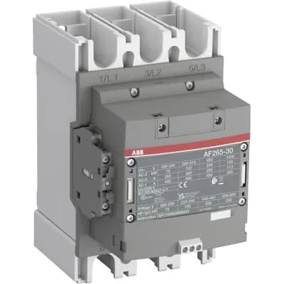
1SFL547002R3122 ABB: The AF265-30-22-31 is a 3 pole - 1000 V IEC or 600 V UL contactor with Main Circuit Bars, controlling motors up to 132 kW / 400 V AC (AC-3) or 200 hp / 480 V UL and switching power circuits up to 400 A (AC-1) or 350 A UL general use. Thanks to the AF technology, the contactor has a wide control voltage range (24-60 V 50/60 Hz and 20-60 V DC), managing large control voltage variations, reducing panel energy consumptions and ensuring distinct operations in unstable networks. Furthermore, surge protection is built-in, offering a compact solution. AF contactors have a block type design, can be easily extended with add-on auxiliary contact blocks and an additional wide range of accessories.
Minimum Order Quantity
1 piece
Customs Tariff Number
8536490099
Data Sheet, Technical Information
1SBC100214C0202 - Main catalog Motor protection and control Manual motor starters, contactors and overload relays (PDF) - Edition 2024
Data Sheet, Technical Information (Part 2)
Contactors and Overload relays guide
Instructions and Manuals
Operating instruction, Contactor, AF(S)190 ... AF(S)370
CAD Dimensional Drawing
Information - 2D and 3D files for CAD systems
Product Net Width
160 mm
Product Net Depth / Length
191 mm
Product Net Height
225 mm
Product Net Weight
3.9 kg
Number of Main Contacts NO
3
Number of Main Contacts NC
0
Number of Auxiliary Contacts NO
2
Number of Auxiliary Contacts NC
2
Number of Poles
3P
Rated Operational Voltage
Main Circuit 1000 V
Rated Frequency (f)
Main Circuit 50 / 60 Hz
Conventional Free-air Thermal Current (Ith)
acc. to IEC 60947-4-1, Open Contactors Θ = 40 °C 400 A
Rated Operational Current AC-1 (Ie)
(1000 V) 40 °C 350 A | (1000 V) 60 °C 300 A | (1000 V) 70 °C 240 A | (690 V) 40 °C 400 A | (690 V) 60 °C 350 A | (690 V) 70 °C 290 A
Rated Operational Current AC-3 (Ie)
(415 V) 60 °C 265 A | (440 V) 60 °C 265 A | (500 V) 60 °C 250 A | (690 V) 60 °C 250 A | (1000 V) 60 °C 113 A | (380 / 400 V) 60 °C 265 A | (220 / 230 / 240 V) 60 °C 265 A
Rated Operational Power AC-3 (Pe)
(415 V) 132 kW | (440 V) 160 kW | (500 V) 160 kW | (690 V) 200 kW | (1000 V) 160 kW | (380 / 400 V) 132 kW | (220 / 230 / 240 V) 75 kW
Rated Breaking Capacity AC-3
8 x Ie AC-3
Rated Making Capacity AC-3
10 x Ie AC-3
Rated Short-time Withstand Current Low Voltage (Icw)
at 40 °C Ambient Temp, in Free Air, from a Cold State 10 s 2120 A | at 40 °C Ambient Temp, in Free Air, from a Cold State 15 min 400 A | at 40 °C Ambient Temp, in Free Air, from a Cold State 1 min 865 A | at 40 °C Ambient Temp, in Free Air, from a Cold State 1 s 2650 A | at 40 °C Ambient Temp, in Free Air, from a Cold State 30 s 1224 A
Maximum Breaking Capacity
cos phi=0.45 (cos phi=0.35 for Ie > 100 A) at 440 V 3800 A | cos phi=0.45 (cos phi=0.35 for Ie > 100 A) at 690 V 3300 A
Rated Insulation Voltage (Ui)
acc. to IEC 60947-4-1 and VDE 0110 (Gr. C) 1000 V | acc. to UL/CSA 1000 V
Rated Impulse Withstand Voltage (Uimp)
Main Circuit 8 kV
Maximum Electrical Switching Frequency
(AC-1) 300 cycles per hour | (AC-2 / AC-4) 150 cycles per hour | (AC-3) 300 cycles per hour
Mechanical Durability
5 million
Maximum Mechanical Switching Frequency
300 cycles per hour
Rated Control Circuit Voltage (Uc)
50 Hz 24 ... 60 V | 60 Hz 24...60 V | DC Operation 20...60 V
Coil Consumption
Holding at Max. Rated Control Circuit Voltage 50 Hz 9 V·A | Holding at Max. Rated Control Circuit Voltage 50 Hz 3 W | Holding at Max. Rated Control Circuit Voltage 60 Hz 9 V·A | Holding at Max. Rated Control Circuit Voltage 60 Hz 3 W | Holding at Max. Rated Control Circuit Voltage DC 3.5 W | Pull-in at Max. Rated Control Circuit Voltage 50 Hz 475 V·A | Pull-in at Max. Rated Control Circuit Voltage 60 Hz 475 V·A | Pull-in at Max. Rated Control Circuit Voltage DC 400 W
Power Loss
at Rated Operating Conditions AC-1 per Pole 32 W | at Rated Operating Conditions AC-3 per Pole 14 W
Operate Time
Between Coil De-energization and NO Contact Opening 45 ... 80 ms | Between Coil Energization and NO Contact Closing 30 ... 60 ms
Connecting Capacity Auxiliary Circuit
Flexible with Ferrule 1x 0.75 ... 2.5 mm² | Flexible with Ferrule 2x 0.75 ... 2.5 mm² | Flexible with Insulated Ferrule 1x 0.75 ... 2.5 mm² | Flexible with Insulated Ferrule 2x 0.75 ... 2.5 mm² | Flexible 1x 0.75 ... 2.5 mm² | Flexible 2x 0.75 ... 2.5 mm² | Solid 1x 1 ... 4 mm² | Solid 2x 1 ... 4 mm² | Stranded 1x 1 ... 4 mm² | Stranded 2x 1 ... 4 mm²
Connecting Capacity
Flexible 2 x 70 ... 185 mm² | Rigid Al-Cable 1 x 185 ... 240 mm² | Rigid Cu-Cable 2 x 70 ... 185 mm²
Wire Stripping Length
Auxiliary Circuit 9 mm | Control Circuit 9 mm
Degree of Protection
acc. to IEC 60529, IEC 60947-1, EN 60529 Coil Terminals IP20 | acc. to IEC 60529, IEC 60947-1, EN 60529 Main Terminals IP00
Recommended Screw Driver
Main Circuit M10 | Control Circuit M3.5
Tightening Torque
Auxiliary Circuit 1 N·m | Cable Lug 28 N·m | Control Circuit 1 N·m | Main Circuit 22 ... 43 N·m
Terminal Type
Main Circuit: Bars
Product Name
Block Contactor
NEMA Size
5
Continuous Current Rating NEMA
270 A
Horsepower Rating NEMA
(200 V AC) Three Phase 75 Hp | (230 V AC) Three Phase 100 Hp | (460 V AC) Three Phase 200 Hp | (575 V AC) Three Phase 200 Hp
Maximum Operating Voltage UL/CSA
Main Circuit 1000 V
General Use Rating UL/CSA
(1000 V AC) 350 A
Horsepower Rating UL/CSA
(200 ... 208 V AC) Three Phase 75 hp | (220 ... 240 V AC) Three Phase 100 hp | (440 ... 480 V AC) Three Phase 200 hp | (550 ... 600 V AC) Three Phase 250 hp
Tightening Torque UL/CSA
Auxiliary Circuit 9 in·lb | Control Circuit 9 in·lb | Main Circuit 372 in·lb
Full Load Amps Motor Use
(200 ... 208 V AC) Three Phase 221 A | (220 ... 240 V AC) Three Phase 248 A | (440 ... 480 V AC) Three Phase 240 A | (550 ... 600 V AC) Three Phase 242 A
Ambient Air Temperature
Close to Contactor Fitted with Thermal O/L Relay (0.85 ... 1.1 Uc) -25 ... 55 °C | Close to Contactor without Thermal O/L Relay (0.85 ... 1.1 Uc) -40 ... 70 °C | Close to Contactor for Storage -40 ... 70 °C
Maximum Operating Altitude Permissible
Without Derating 3000 m
Conflict Minerals Reporting Template (CMRT)
CMRT - Conflict Minerals Reporting Template
REACH Declaration
REACH - Letter of Confirmation for block contactors, contactor relays, installation contactors, mini contactors, mini contactor relays, thermal overload relays, electronic overload relays and related accessories
RoHS Information
RoHS II declaration for block contactors, installation contactors, mini contactors, mini contactor relays, thermal overload relays, electronic overload relays and related accessories
RoHS Status
Following EU Directive 2011/65/EU and Amendment 2015/863 July 22, 2019
Toxic Substances Control Act - TSCA
Toxic Substances Control Act (TSCA) declaration for Contactors
WEEE B2C / B2B
Business To Business
WEEE Category
5. Small Equipment (No External Dimension More Than 50 cm)
ABB EcoSolutions
Yes
ABB Site Meeting Group Waste To Landfill Target
Non-hazardous waste is sent to a landfill, where there is no alternative option available within 100km of a facility
End Of Life Disassembling Instructions
End-of-life instruction - AF(S)265(B)-**(RT) to AF(S)370(B)-**(RT)
Environmental Product Declaration - EPD
Environmental Product Declaration, Contactors, AF(S)265-AF(S)370 (SE)
Improved Energy Efficiency for Customers
Product Efficiency - Product considered more energy-efficient compared to similar product on market or older products from the same line
Recyclability Rate of the Product acc. to EN45555
Design for Closing Resource Loops - Standard EN45555 - 76.3 %
Sustainable Material Content in Product (wt. %)
Recycled Metal - 33 %
A2L Certificate – UL
UL Certificate of Compliance A2L, Contactor, AF190 - AF370
Declaration of Conformity - CE
CE Declaration of Conformity - Contactor - AF116...AF370
Declaration of Conformity - UKCA
UK Declaration of Conformity - Contactors >100A
UL Certificate
cULus Certificate, Contactor, AF265, AF305, AF370, AX260, AX300, AX370, AFS265, AFS305, AFS370
Package Level 1 Units
box 1 piece
Package Level 1 Width
263 mm
Package Level 1 Depth / Length
203 mm
Package Level 1 Height
289 mm
Package Level 1 Gross Weight
4.6 kg
Package Level 1 EAN
7320500561799
Object Classification Code
Q
ETIM 7
EC000066 - Power contactor, AC switching
ETIM 8
EC000066 - Power contactor, AC switching
ETIM 9
EC000066 - Power contactor, AC switching
eClass
V11.0 : 27371003
UNSPSC
39121529
IDEA Granular Category Code (IGCC)
4758 >> Iec Contactors
Feature: AF technology provides a wide control voltage range of 24 … 60 V for AC operation and 20 … 60 V for DC operation. Business Impact: It tolerates large control voltage variations, reducing panel energy consumption and minimizing nuisance trips in unstable networks. Application: Suitable for HVAC drives, pumps, and conveyor systems where supply fluctuation is common. Feature: Built-in surge protection and a compact AF block design. Business Impact: Increases reliability and reduces need for separate surge suppression components, lowering panel size and maintenance. Application: Ideal for substations, packaging lines, and robotics cells with dense control gear. Feature: Three main contacts (NO) and two auxiliary contacts (NO/NC), rated up to 1000 V and AC-3 power switching. Business Impact: Enables efficient motor starting and reliable control circuit monitoring with extended diagnostics potential. Application: Motor starters in heavy machinery and process lines. Feature: Main circuit bars connection, specified dimensions (160 mm width, 191 mm depth, 225 mm height) and 3.9 kg weight. Business Impact: Streamlines panel layout, reduces mounting time, and simplifies integration with existing busbars and cable management. Application: New installations and retrofits in switchgear panels. Feature: High durability with IEC/UL compliance and robust mechanical life (up to 5 million cycles). Business Impact: Maximizes uptime and lowers maintenance costs for mission-critical equipment. Application: Continuous operation in packaging, material handling, and water treatment systems. Feature: Compliance and documentation coverage (CE, UKCA, UL/CSA, RoHS, REACH) and end-of-life instructions. Business Impact: Eases regulatory approvals and sustainability reporting, supporting traceability and responsible procurement. Application: Global projects with strict conformity requirements across regions.
Get a Quick Quote for a ABB 1SFL547002R3122
Chat with us on WhatsApp - fast responses guaranteed
Need to speak with someone? We'll call you back within 2 hours during business hours
Interested in ABB 1SFL547002R3122?
Enquire Now
FAQs
The AF265-30-22-31 uses main circuit bars for the bus connection with a compact footprint (160 mm wide, 191 mm deep, 225 mm high) and a weight of 3.9 kg. Auxiliary connections support flexible wiring with ferrule or insulated ferrules from 0.75 to 2.5 mm², and a defined stripping length of 9 mm for consistent terminations.
Rated Operational Current AC-1 at 1000 V ranges from 300 A up to 350 A depending on ambient temperature, while AC-3 current ratings reach 265 A at 415–690 V and 113 A at 1000 V, with corresponding power ratings up to 132 kW at 400 V. This supports reliable motor starting and switching in common industrial drives.
Yes. The device carries CE and UKCA conformity with UL/CSA listings for global deployment, and a UL certificate is specified for multiple model variants. This ensures compliance with regional electrical codes and simplifies procurement for multinational projects.
AF technology enables a wide control voltage range, reducing control circuit energy consumption. Mechanical durability is rated at about 5 million cycles, supporting long service life. The device also integrates surge protection, reducing wear on contacts and extending overall equipment life in variable power networks.
The product ships with CE and UKCA declarations, UL certificates, and environmental declarations (REACH, RoHS) along with end-of-life and recycling guidance. Additional data sheets, installation instructions, and CAD drawings are available to support engineering validation and compliant deployment.