ABB AF265-30-22-32 Contactor - 1000 V AF technology
Part Number: 1SFL547002R3222
Quick Summary
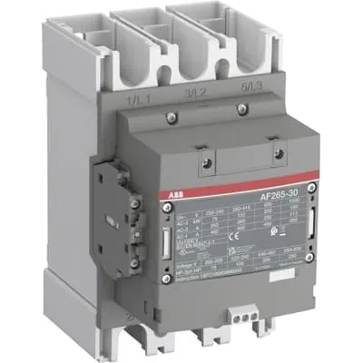
ABB AF265-30-22-32 Contactor is a 3-pole motor control device designed for high-performance switching in industrial automation. It delivers reliable operation across varying control voltages and network conditions, reducing startup glitches and energy waste in demanding panels. The AF technology enables a wide control voltage range (48-130 V AC/DC), helping you cope with fluctuations without compromising control accuracy. This unit carries important certifications and standards, including CE declarations, UL/CSA listings, and RoHS/REACH compliance, ensuring safe, compliant installation in global facilities. For system integrators and procurement teams, the AF265-30-22-32 offers plug-in compatibility with add-on auxiliary contact blocks and a compact footprint that lowers panel size and wiring complexity while improving uptime and serviceability.
Product Information
Extended Description
1SFL547002R3222 ABB: The AF265-30-22-32 is a 3 pole - 1000 V IEC or 600 V UL contactor with Main Circuit Bars, controlling motors up to 132 kW / 400 V AC (AC-3) or 200 hp / 480 V UL and switching power circuits up to 400 A (AC-1) or 350 A UL general use. Thanks to the AF technology, the contactor has a wide control voltage range (48-130 V 50/60 Hz and DC), managing large control voltage variations, reducing panel energy consumptions and ensuring distinct operations in unstable networks. Furthermore, surge protection is built-in, offering a compact solution. AF contactors have a block type design, can be easily extended with add-on auxiliary contact blocks and an additional wide range of accessories.
Minimum Order Quantity
1 piece
Customs Tariff Number
8536490099
Data Sheet, Technical Information
1SBC100214C0202 - Main catalog Motor protection and control Manual motor starters, contactors and overload relays (PDF) - Edition 2024
Data Sheet, Technical Information (Part 2)
Contactors and Overload relays guide
Instructions and Manuals
Operating instruction, Contactor, AF(S)190 ... AF(S)370
CAD Dimensional Drawing
Information - 2D and 3D files for CAD systems
Product Net Width
160 mm
Product Net Depth / Length
191 mm
Product Net Height
225 mm
Product Net Weight
3.9 kg
Number of Main Contacts NO
3
Number of Main Contacts NC
0
Number of Auxiliary Contacts NO
2
Number of Auxiliary Contacts NC
2
Number of Poles
3P
Rated Operational Voltage
Main Circuit 1000 V
Rated Frequency (f)
Main Circuit 50 / 60 Hz
Conventional Free-air Thermal Current (Ith)
acc. to IEC 60947-4-1, Open Contactors Θ = 40 °C 400 A
Rated Operational Current AC-1 (Ie)
(1000 V) 40 °C 350 A | (1000 V) 60 °C 300 A | (1000 V) 70 °C 240 A | (690 V) 40 °C 400 A | (690 V) 60 °C 350 A | (690 V) 70 °C 290 A
Rated Operational Current AC-3 (Ie)
(415 V) 60 °C 265 A | (440 V) 60 °C 265 A | (500 V) 60 °C 250 A | (690 V) 60 °C 250 A | (1000 V) 60 °C 113 A | (380 / 400 V) 60 °C 265 A | (220 / 230 / 240 V) 60 °C 265 A
Rated Operational Power AC-3 (Pe)
(415 V) 132 kW | (440 V) 160 kW | (500 V) 160 kW | (690 V) 200 kW | (1000 V) 160 kW | (380 / 400 V) 132 kW | (220 / 230 / 240 V) 75 kW
Rated Breaking Capacity AC-3
8 x Ie AC-3
Rated Making Capacity AC-3
10 x Ie AC-3
Rated Short-time Withstand Current Low Voltage (Icw)
at 40 °C Ambient Temp, in Free Air, from a Cold State 10 s 2120 A | at 40 °C Ambient Temp, in Free Air, from a Cold State 15 min 400 A | at 40 °C Ambient Temp, in Free Air, from a Cold State 1 min 865 A | at 40 °C Ambient Temp, in Free Air, from a Cold State 1 s 2650 A | at 40 °C Ambient Temp, in Free Air, from a Cold State 30 s 1224 A
Maximum Breaking Capacity
cos phi=0.45 (cos phi=0.35 for Ie > 100 A) at 440 V 3800 A | cos phi=0.45 (cos phi=0.35 for Ie > 100 A) at 690 V 3300 A
Rated Insulation Voltage (Ui)
acc. to IEC 60947-4-1 and VDE 0110 (Gr. C) 1000 V | acc. to UL/CSA 1000 V
Rated Impulse Withstand Voltage (Uimp)
Main Circuit 8 kV
Maximum Electrical Switching Frequency
(AC-1) 300 cycles per hour | (AC-2 / AC-4) 150 cycles per hour | (AC-3) 300 cycles per hour
Mechanical Durability
5 million
Maximum Mechanical Switching Frequency
300 cycles per hour
Rated Control Circuit Voltage (Uc)
50 Hz 48 ... 130 V | 60 Hz 48 ... 130 V | DC Operation 48 ... 130 V
Coil Consumption
Holding at Max. Rated Control Circuit Voltage 50 Hz 17 V·A | Holding at Max. Rated Control Circuit Voltage 50 Hz 3 W | Holding at Max. Rated Control Circuit Voltage 60 Hz 17 V·A | Holding at Max. Rated Control Circuit Voltage 60 Hz 3 W | Holding at Max. Rated Control Circuit Voltage DC 2.5 W | Pull-in at Max. Rated Control Circuit Voltage 50 Hz 340 V·A | Pull-in at Max. Rated Control Circuit Voltage 60 Hz 340 V·A | Pull-in at Max. Rated Control Circuit Voltage DC 360 W
Power Loss
at Rated Operating Conditions AC-1 per Pole 32 W | at Rated Operating Conditions AC-3 per Pole 14 W
Operate Time
Between Coil De-energization and NO Contact Opening 45 ... 80 ms | Between Coil Energization and NO Contact Closing 30 ... 60 ms
Connecting Capacity Auxiliary Circuit
Flexible with Ferrule 1x 0.75 ... 2.5 mm² | Flexible with Ferrule 2x 0.75 ... 2.5 mm² | Flexible with Insulated Ferrule 1x 0.75 ... 2.5 mm² | Flexible with Insulated Ferrule 2x 0.75 ... 2.5 mm² | Flexible 1x 0.75 ... 2.5 mm² | Flexible 2x 0.75 ... 2.5 mm² | Solid 1x 1 ... 4 mm² | Solid 2x 1 ... 4 mm² | Stranded 1x 1 ... 4 mm² | Stranded 2x 1 ... 4 mm²
Connecting Capacity
Flexible 2 x 70 ... 185 mm² | Rigid Al-Cable 1 x 185 ... 240 mm² | Rigid Cu-Cable 2 x 70 ... 185 mm²
Wire Stripping Length
Auxiliary Circuit 9 mm | Control Circuit 9 mm
Degree of Protection
acc. to IEC 60529, IEC 60947-1, EN 60529 Coil Terminals IP20 | acc. to IEC 60529, IEC 60947-1, EN 60529 Main Terminals IP00
Recommended Screw Driver
Main Circuit M10 | Control Circuit M3.5
Tightening Torque
Auxiliary Circuit 1 N·m | Cable Lug 28 N·m | Control Circuit 1 N·m | Main Circuit 22 ... 43 N·m
Terminal Type
Main Circuit: Bars
Product Name
Block Contactor
NEMA Size
5
Continuous Current Rating NEMA
270 A
Horsepower Rating NEMA
(200 V AC) Three Phase 75 Hp | (230 V AC) Three Phase 100 Hp | (460 V AC) Three Phase 200 Hp | (575 V AC) Three Phase 200 Hp
Maximum Operating Voltage UL/CSA
Main Circuit 1000 V
General Use Rating UL/CSA
(1000 V AC) 350 A
Horsepower Rating UL/CSA
(200 ... 208 V AC) Three Phase 75 hp | (220 ... 240 V AC) Three Phase 100 hp | (440 ... 480 V AC) Three Phase 200 hp | (550 ... 600 V AC) Three Phase 250 hp
Tightening Torque UL/CSA
Auxiliary Circuit 9 in·lb | Control Circuit 9 in·lb | Main Circuit 372 in·lb
Full Load Amps Motor Use
(200 ... 208 V AC) Three Phase 221 A | (220 ... 240 V AC) Three Phase 248 A | (440 ... 480 V AC) Three Phase 240 A | (550 ... 600 V AC) Three Phase 242 A
Ambient Air Temperature
Close to Contactor Fitted with Thermal O/L Relay (0.85 ... 1.1 Uc) -25 ... 55 °C | Close to Contactor without Thermal O/L Relay (0.85 ... 1.1 Uc) -40 ... 70 °C | Close to Contactor for Storage -40 ... 70 °C
Maximum Operating Altitude Permissible
Without Derating 3000 m
Conflict Minerals Reporting Template (CMRT)
CMRT - Conflict Minerals Reporting Template
REACH Declaration
REACH - Letter of Confirmation for block contactors, contactor relays, installation contactors, mini contactors, mini contactor relays, thermal overload relays, electronic overload relays and related accessories
RoHS Information
RoHS II declaration for block contactors, installation contactors, mini contactors, mini contactor relays, thermal overload relays, electronic overload relays and related accessories
RoHS Status
Following EU Directive 2011/65/EU and Amendment 2015/863 July 22, 2019
Toxic Substances Control Act - TSCA
Toxic Substances Control Act (TSCA) declaration for Contactors
WEEE B2C / B2B
Business To Business
WEEE Category
5. Small Equipment (No External Dimension More Than 50 cm)
ABB EcoSolutions
Yes
ABB Site Meeting Group Waste To Landfill Target
Non-hazardous waste is sent to a landfill, where there is no alternative option available within 100km of a facility
End Of Life Disassembling Instructions
End-of-life instruction - AF(S)265(B)-**(RT) to AF(S)370(B)-**(RT)
Environmental Product Declaration - EPD
Environmental Product Declaration, Contactors, AF(S)265-AF(S)370 (SE)
Improved Energy Efficiency for Customers
Product Efficiency - Product considered more energy-efficient compared to similar product on market or older products from the same line
Recyclability Rate of the Product acc. to EN45555
Design for Closing Resource Loops - Standard EN45555 - 76.3 %
Sustainable Material Content in Product (wt. %)
Recycled Metal - 33 %
A2L Certificate – UL
UL Certificate of Compliance A2L, Contactor, AF190 - AF370
Declaration of Conformity - CE
CE Declaration of Conformity - Contactor - AF116...AF370
Declaration of Conformity - UKCA
UK Declaration of Conformity - Contactors >100A
UL Certificate
cULus Certificate, Contactor, AF265, AF305, AF370, AX260, AX300, AX370, AFS265, AFS305, AFS370
Package Level 1 Units
box 1 piece
Package Level 1 Width
263 mm
Package Level 1 Depth / Length
203 mm
Package Level 1 Height
289 mm
Package Level 1 Gross Weight
4.6 kg
Package Level 1 EAN
7320500561829
Object Classification Code
Q
ETIM 7
EC000066 - Power contactor, AC switching
ETIM 8
EC000066 - Power contactor, AC switching
ETIM 9
EC000066 - Power contactor, AC switching
eClass
V11.0 : 27371003
UNSPSC
39121529
IDEA Granular Category Code (IGCC)
4758 >> Iec Contactors
Feature → Business Impact → Application: AF265-30-22-32 uses AF technology to tolerate wide control voltage variations (48-130 V AC/DC), enabling stable coil operation and reduced panel energy consumption in environments with unstable supply. This translates to fewer nuisance trips, longer motor life, and lower maintenance costs in packaging, metalworking, and material handling applications. Feature → Built-in surge protection in a compact block design → Improves uptime and protects downstream circuits from voltage spikes, reducing transformer wear and fuse replacements in critical conveyor lines and automated machining cells. Feature → 3 NO main contacts and 2 NO auxiliary contacts → Simplifies wiring and control logic while supporting extended control circuits for complex start/stop sequences and interlocking in multi-axis systems. Feature → Wide ambient operation (-25 to 55 °C with O/L relay, -40 to 70 °C without) → Maintains consistent performance in harsh factory floors, ensuring reliable operation in outdoor or remote installations. Feature → Main circuit rated up to 1000 V and AC-3 current up to 265 A (varies by voltage) → Enables high-power motor starting for pumps, fans, and compressors with safe electrical margins and predictable thermal behavior. Feature → Fuel-efficient coil consumption and defined pull-in/push-out times (pull-in 340 V·A, hold 3 W) → Reduces energy draw in idle periods and improves synchronized control with PLCs and soft starters. Feature → 3P, 3 main NO contacts with 2 NO auxiliaries, integrated with add-on auxiliary blocks → Streamlines expansion for future control logic or remote signaling without rearranging the panel, delivering longer asset life and lower retrofit costs. Feature → Compliance to IEC 60947-4-1, UL/CSA, CE, REACH, RoHS, and TSCA declarations → Guarantees regulatory alignment, faster audits, and safer procurement decisions for multi-site deployments. Feature → 300 cycles/hour (AC-1) and 300 cycles/hour (AC-3) mechanical and electrical switching symmetry → Supports consistent cycle life in automation lines with frequent start/stop cycles, improving overall equipment effectiveness (OEE).
Get a Quick Quote for a ABB 1SFL547002R3222
Chat with us on WhatsApp - fast responses guaranteed
Need to speak with someone? We'll call you back within 2 hours during business hours
Interested in ABB 1SFL547002R3222?
Enquire Now
FAQs
Plan for 3P alignment with main circuit bars and ensure the main terminals are IP00 protected while coil terminals are IP20. Use the recommended M10 tool for main circuit connections and M3.5 for control circuit terminals. Leave adequate clearance for heat dissipation and plan for 30-60 ms switching transients during operation to minimize arcing.
Rated Operational Current AC-3 varies by voltage (e.g., 113 A at 1000 V, 265 A at 440–690 V) with corresponding rated power up to 200 kW at 690 V. It also provides a 8 x Ie breaking capacity and 10 x Ie making capacity for AC-3, ensuring reliable motor starting and stopping under typical industrial loads.
Yes. It is designed for main circuits up to 1000 V and supports high-inertia motor control via AC-3 ratings. The device’s 3-pole design, 3 NO main contacts, and robust mechanical life (up to 5 million cycles) make it appropriate for demanding applications like pumps and compressors in steel, cement, or plastics processing.
CE Declaration of Conformity, UL/CSA listing, and UKCA/UL certifications apply. The product also complies with RoHS II, REACH declarations, TSCA positioning, and WEEE Business-to-Business guidelines, supported by material declarations and EPDs for eco-design considerations.
Improvements come from reduced energy consumption in control circuits due to optimized coil consumption, fewer outages thanks to surge protection and wide voltage tolerance, and lower maintenance from extended mechanical life. The compact footprint also decreases panel size, reducing enclosure costs and wiring complexity over time.