ABB AF265B-40-22RT-12 Contactor - UL/CE Certified
Part Number: 1SFL547262R1222
Quick Summary
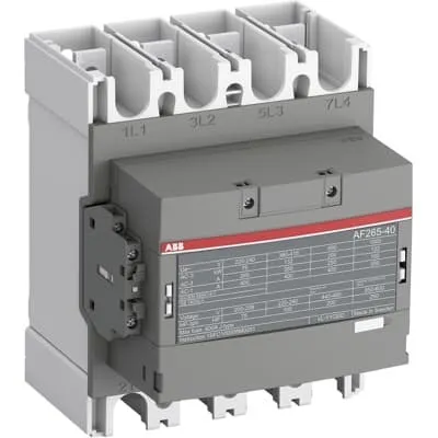
AF265B-40-22RT-12 Contactor is a four-pole motor controller designed for industrial drives up to 132 kW at 400 V AC (AC-3). Engineers often grapple with voltage fluctuations and energy waste in control panels; this device’s wide control voltage range, from 48 to 130 V across AC and DC, minimizes nuisance trips and reduces overall energy consumption. The AF technology enables a broad control margin while delivering reliable operation in unstable networks. With built-in surge protection and a compact, extendable block design, it supports easy customization through add-on auxiliary contact blocks. Compatibility with standard panel layouts helps cut wiring complexity and total cost of ownership while maintaining robust protection for high-demand equipment.
Product Information
Extended Description
1SFL547262R1222 ABB: The AF265B-40-22RT-12 is a 4 pole - 1000 V IEC or 600 V UL contactor with pre-mounted auxiliary contacts and ring tongue ferrules, controlling motors up to 132 kW / 400 V AC (AC-3) / and switching power circuits up to 400 A (AC-1) or 300 A UL general use. Thanks to the AF technology, the contactor has a wide control voltage range (48-130 V 50/60 Hz and DC), managing large control voltage variations, reducing panel energy consumptions and ensuring distinct operations in unstable networks. Furthermore, surge protection is built-in, offering a compact solution. AF contactors have a block type design, can be easily extended with add-on auxiliary contact blocks and an additional wide range of accessories.
Minimum Order Quantity
1 piece
Customs Tariff Number
85364900
Data Sheet, Technical Information
1SBC100214C0202 - Main catalog Motor protection and control Manual motor starters, contactors and overload relays (PDF) - Edition 2024
Data Sheet, Technical Information (Part 2)
Contactors and Overload relays guide
Instructions and Manuals
Operating instruction, Contactor, AF(S)190 ... AF(S)370
CAD Dimensional Drawing
Information - 2D and 3D files for CAD systems
Product Net Width
184 mm
Product Net Depth / Length
180 mm
Product Net Height
225 mm
Product Net Weight
5.7 kg
Number of Main Contacts NO
4
Number of Main Contacts NC
0
Number of Auxiliary Contacts NO
2
Number of Auxiliary Contacts NC
2
Number of Poles
4P
Rated Operational Voltage
Main Circuit 1000 V
Rated Operational Current AC-1 (Ie)
(1000 V) 40 °C 350 A | (1000 V) 60 °C 300 A | (1000 V) 70 °C 240 A | (690 V) 40 °C 400 A | (690 V) 60 °C 350 A | (690 V) 70 °C 290 A
Rated Operational Current AC-3 (Ie)
(415 V) 55 °C 265 A | (440 V) 55 °C 265 A | (500 V) 55 °C 250 A | (690 V) 55 °C 250 A | (380 / 400 V) 55 °C 265 A | (220 / 230 / 240 V) 55 °C 265 A
Rated Operational Current DC-1 (Ie)
(100 V) 1 Pole, 40 °C 400 A | (100 V) 1 Pole, 60 °C 350 A | (100 V) 1 Pole, 70 °C 290 A | (110 V) 1-Pole, 40 °C 400 A | (110 V) 1-Pole, 60 °C 350 A | (110 V) 1-Pole, 70 °C 290 A | (110 V) 2 Poles in Series, 40 °C 400 A | (110 V) 2 Poles in Series, 60 °C 350 A | (110 V) 2 Poles in Series, 70 °C 290 A | (110 V) 3 Poles in Series, 40 °C 400 A | (110 V) 3 Poles in Series, 60 °C 350 A | (110 V) 3 Poles in Series, 70 °C 290 A | (175 V) 2 Poles in Series, 40 °C 400 A | (175 V) 2 Poles in Series, 60 °C 350 A | (175 V) 2 Poles in Series, 70 °C 290 A | (200 V) 2 Poles in Series, 40 °C 400 A | (200 V) 2 Poles in Series, 60 °C 350 A | (200 V) 2 Poles in Series, 70 °C 290 A | (220 V) 2 Poles in Series, 40 °C 400 A | (220 V) 2 Poles in Series, 60 °C 350 A | (220 V) 2 Poles in Series, 70 °C 290 A | (220 V) 3 Poles in Series, 40 °C 400 A | (220 V) 3 Poles in Series, 60 °C 350 A | (220 V) 3 Poles in Series, 70 °C 290 A | (260 V) 3 Poles in Series, 40 °C 400 A | (260 V) 3 Poles in Series, 60 °C 350 A | (260 V) 3 Poles in Series, 70 °C 290 A | (300 V) 3 Poles in Series, 40 °C 400 A | (300 V) 3 Poles in Series, 60 °C 350 A | (300 V) 3 Poles in Series, 70 °C 290 A | (340 V) 3 Poles in Series, 40 °C 400 A | (340 V) 3 Poles in Series, 60 °C 350 A | (340 V) 3 Poles in Series, 70 °C 290 A | (350 V) 4 Poles in Series, 40 °C 400 A | (350 V) 4 Poles in Series, 60 °C 350 A | (350 V) 4 Poles in Series, 70 °C 290 A | (400 V) 4 Poles in Series, 40 °C 400 A | (400 V) 4 Poles in Series, 60 °C 350 A | (400 V) 4 Poles in Series, 70 °C 290 A | (440 V) 4 Poles in Series, 40 °C 400 A | (440 V) 4 Poles in Series, 60 °C 350 A | (440 V) 4 Poles in Series, 70 °C 290 A | (72 V) 1-Pole, 40 °C 400 A | (72 V) 1-Pole, 60 °C 350 A | (72 V) 1-Pole, 70 °C 290 A | (72 V) 2 Poles in Series, 40 °C 400 A | (72 V) 2 Poles in Series, 60 °C 350 A | (72 V) 2 Poles in Series, 70 °C 290 A | (72 V) 3 Poles in Series, 40 °C 400 A | (72 V) 3 Poles in Series, 60 °C 350 A | (72 V) 3 Poles in Series, 70 °C 290 A | (90 V) 1 Pole, 40 °C 400 A | (90 V) 1 Pole, 60 °C 350 A | (90 V) 1 Pole, 70 °C 290 A
Rated Operational Current DC-3 (Ie)
(110 V) 2 Poles in Series, 40 °C 350 A | (110 V) 2 Poles in Series, 60 °C 350 A | (110 V) 2 Poles in Series, 70 °C 290 A | (110 V) 3 Poles in Series, 40 °C 350 A | (110 V) 3 Poles in Series, 60 °C 350 A | (110 V) 3 Poles in Series, 70 °C 290 A | (220 V) 3 Poles in Series, 40 °C 350 A | (220 V) 3 Poles in Series, 60 °C 350 A | (220 V) 3 Poles in Series, 70 °C 290 A | (72 V) 2 Poles in Series, 40 °C 350 A | (72 V) 2 Poles in Series, 60 °C 350 A | (72 V) 2 Poles in Series, 70 °C 290 A | (72 V) 3 Poles in Series, 40 °C 350 A | (72 V) 3 Poles in Series, 60 °C 350 A | (72 V) 3 Poles in Series, 70 °C 290 A
Rated Operational Current DC-5 (Ie)
(110 V) 2 Poles in Series, 40 °C 350 A | (110 V) 2 Poles in Series, 60 °C 350 A | (110 V) 2 Poles in Series, 70 °C 290 A | (110 V) 3 Poles in Series, 40 °C 350 A | (110 V) 3 Poles in Series, 60 °C 350 A | (110 V) 3 Poles in Series, 70 °C 290 A | (220 V) 3 Poles in Series, 40 °C 350 A | (220 V) 3 Poles in Series, 60 °C 350 A | (220 V) 3 Poles in Series, 70 °C 290 A | (72 V) 2 Poles in Series, 40 °C 350 A | (72 V) 2 Poles in Series, 60 °C 350 A | (72 V) 2 Poles in Series, 70 °C 290 A | (72 V) 3 Poles in Series, 40 °C 350 A | (72 V) 3 Poles in Series, 60 °C 350 A | (72 V) 3 Poles in Series, 70 °C 290 A
Rated Operational Power AC-3 (Pe)
(415 V) 132 kW | (380 / 400 V) 132 kW | (220 / 230 / 240 V) 75 kW
Rated Short-time Withstand Current Low Voltage (Icw)
at 40 °C Ambient Temp, in Free Air, from a Cold State 10 s 2120 A | at 40 °C Ambient Temp, in Free Air, from a Cold State 15 min 400 A | at 40 °C Ambient Temp, in Free Air, from a Cold State 1 min 865 A | at 40 °C Ambient Temp, in Free Air, from a Cold State 1 s 2650 A | at 40 °C Ambient Temp, in Free Air, from a Cold State 30 s 1224 A
Rated Insulation Voltage (Ui)
acc. to UL/CSA 1000 V
Mechanical Durability
5 million
Maximum Mechanical Switching Frequency
300 cycles per hour
Rated Control Circuit Voltage (Uc)
50 Hz / 60 Hz 48 ... 130 V | DC Operation 48 ... 130 V
Coil Consumption
Holding at Max. Rated Control Circuit Voltage 50 Hz 17 V·A | Holding at Max. Rated Control Circuit Voltage 60 Hz 17 V·A | Pull-in at Max. Rated Control Circuit Voltage 50 Hz 180 V·A | Pull-in at Max. Rated Control Circuit Voltage 60 Hz 180 V·A | Pull-in at Max. Rated Control Circuit Voltage DC 150 W
Power Loss
32 W | at Rated Operating Conditions per Pole 32 W
Terminal Type
Main Circuit: Bars
Product Name
Block Contactor
Horsepower Rating NEMA
(200 V AC) Three Phase 75 Hp | (230 V AC) Three Phase 100 Hp | (460 V AC) Three Phase 200 Hp | (575 V AC) Three Phase 200 Hp
General Use Rating UL/CSA
(1000 V AC) 350 A
Horsepower Rating UL/CSA
(200 ... 208 V AC) Three Phase 40 Hp | (200 V AC) Three Phase 75 hp | (208 V AC) Three Phase 75 hp | (220 ... 240 V AC) Three Phase 40 Hp | (220 ... 240 V AC) Three Phase 100 hp | (440 ... 480 V AC) Three Phase 100 Hp | (440 ... 480 V AC) Three Phase 200 hp | (550 ... 600 V AC) Three Phase 125 Hp | (550 ... 600 V AC) Three Phase 250 hp
Conflict Minerals Reporting Template (CMRT)
CMRT - Conflict Minerals Reporting Template
REACH Declaration
REACH - Letter of Confirmation for block contactors, contactor relays, installation contactors, mini contactors, mini contactor relays, thermal overload relays, electronic overload relays and related accessories
RoHS Information
RoHS II declaration for block contactors, installation contactors, mini contactors, mini contactor relays, thermal overload relays, electronic overload relays and related accessories
RoHS Status
Following EU Directive 2011/65/EU and Amendment 2015/863 July 22, 2019
Toxic Substances Control Act - TSCA
Toxic Substances Control Act (TSCA) declaration for Contactors
WEEE B2C / B2B
Business To Business
WEEE Category
5. Small Equipment (No External Dimension More Than 50 cm)
ABB EcoSolutions
Yes
ABB Site Meeting Group Waste To Landfill Target
Non-hazardous waste is sent to a landfill, where there is no alternative option available within 100km of a facility
End Of Life Disassembling Instructions
End-of-life instruction - AF(S)265(B)-**(RT) to AF(S)370(B)-**(RT)
Environmental Product Declaration - EPD
Environmental Product Declaration, Contactors, AF(S)265-AF(S)370 (SE)
Improved Energy Efficiency for Customers
Product Efficiency - Product considered more energy-efficient compared to similar product on market or older products from the same line
Recyclability Rate of the Product acc. to EN45555
Design for Closing Resource Loops - Standard EN45555 - 76.3 %
Sustainable Material Content in Product (wt. %)
Recycled Metal - 33 %
A2L Certificate – UL
UL Certificate of Compliance A2L, Contactor, AF190 - AF370
CB Certificate
SEMKO_SE-73326
CQC Certificate
CQC Certificate, AC Contactor, AF265-*-*-*,AF305-*-*-*,AF370-*-*-*,AF265B-*-*-*,AF305B-*-*-*,AF370B-*-*-*, Made in Sweden
cURus Certificate
cURus certificate, Contactor, AF265B..RT - AF370B-40...RT
Declaration of Conformity - CCC
CCC Declaration of Conformity, AC Contactor, AF265-*-*-*,AF305-*-*-*,AF370-*-*-*,AF265B-*-*-*,AF305B-*-*-*,AF370B-*-*-*, Made in Sweden
Declaration of Conformity - CE
CE Declaration of Conformity - Contactor - AF116B...RT to AF370B...RT
Declaration of Conformity - UKCA
UK Declaration of Conformity - Contactors >100A - Rail application
EAC Certificate
9AKK107046A8618
UR Certificate
cURus certificate, Contactor, AF265B..RT - AF370B-40...RT
Package Level 1 Units
box 1 piece
Package Level 1 Width
212 mm
Package Level 1 Depth / Length
262 mm
Package Level 1 Height
212 mm
Package Level 1 Gross Weight
6.4 kg
Package Level 1 EAN
7320500510094
Object Classification Code
Q
ETIM 7
EC000066 - Power contactor, AC switching
ETIM 8
EC000066 - Power contactor, AC switching
ETIM 9
EC000066 - Power contactor, AC switching
eClass
V11.0 : 27371003
UNSPSC
39121529
IDEA Granular Category Code (IGCC)
4755 >> Contactors
Feature → Business Impact → Application: The AF265B-40-22RT-12 uses a four-pole main contactor configuration with two auxiliary NO and two NC contacts, enabling reliable control of high-power motors in compact enclosures, reducing footprint and wiring. This translates to lower panel size, easier maintenance, and lower installation costs in conveyor lines and pump stations. Feature → Business Impact → Application: Rated main circuit voltage of 1000 V and AC-3 current up to 265 A at common industrial voltages ensure compatibility with modern plant motors; this supports safe direct switching of large loads without intermediate gear, ideal for single-line motor control in mills and packaging lines. Feature → Business Impact → Application: A wide control circuit voltage range of 48–130 V (AC/DC) minimizes control voltage variance effects, improving reliability in networks with supply fluctuations and enabling seamless integration with existing PLCs and safety relays. Feature → Business Impact → Application: Built-in surge protection and a block-type design allow straightforward expansion with add-on auxiliary contact blocks, enabling scalable control schemes and reduced wiring, which is beneficial for expanding skid-based machinery or retrofits. Feature → Business Impact → Application: AF technology delivers energy-efficient operation by reducing hold and pull-in losses in the coil, contributing to measurable reductions in energy use and cooler panel temperatures in continuous operation environments. Feature → Business Impact → Application: Durability metrics—5 million mechanical cycles and a maximum switching frequency of 300 cycles per hour—translate to longer service life in demanding applications such as conveyors, presses, and hoist systems, lowering maintenance interventions and downtime.
Get a Quick Quote for a ABB 1SFL547262R1222
Chat with us on WhatsApp - fast responses guaranteed
Need to speak with someone? We'll call you back within 2 hours during business hours
Interested in ABB 1SFL547262R1222?
Enquire Now
FAQs
The AF265B-40-22RT-12 is a block-style contactor designed for easy panel mounting. It ships with pre-mounted auxiliary contacts and ring tongue ferrules, and can be extended with add-on auxiliary contact blocks. Install in a standard DIN rail or fixed mounting enclosure, connect the main circuit bars, and wire the control coil within the 48–130 V range to ensure reliable operation across AC/DC control signals.
Key ratings include four NO main contacts, 2 NO/2 NC auxiliary contacts, 4P poles, main circuit rated up to 1000 V, and AC-3 current up to 265 A at 415–440 V. It supports 132 kW motor loads at 400 V AC (AC-3), with a 350 A UL general use rating and robust insulation for industrial circuits.
Yes. It is designed for 380–400 V AC systems with AC-3 duty, delivering up to 132 kW in this voltage range. The device also supports high current at lower voltages and provides reliable switching for large motors used in conveyors, pumps, and processing lines.
The AF265B-40-22RT-12 is CE and UL/CSA certified, with additional approvals including UKCA, cURus, CCC, and EAC where applicable. It also aligns with RoHS 2 compliance to support environmental standards, making it suitable for global deployment.
With a mechanical durability of 5 million cycles and built-in surge protection, maintenance intervals are extended and downtime is reduced. The wide control voltage tolerance minimizes tripping due to supply fluctuations, reducing energy waste and enabling scalable automation, which lowers total cost of ownership over the equipment life cycle.