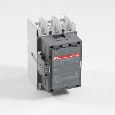
ABB AF300-30-11 Contactor - 690V Main, 500A Ie, CE
Part Number: 1SFL557001R7211
Quick Summary
AF300-30-11 DC contactor provides reliable motor starting and isolation for industrial drives. Many engineers face the challenge of balancing a wide DC coil control range with compact footprint and enduring reliability. It carries CE and UL/CSA safety certifications, plus CB recognition for global compliance. This ABB block contactor delivers space-efficient mounting, easy wiring, and robust performance, reducing panel design time and spare-parts inventory while supporting high-demand applications in manufacturing and process industries.
Product Information
Extended Description
1SFL557001R7211 ABB: A 3-phase Contactor suitable for various applications such as Motor starting, Isolation, By-pass and Distribution application up to max 690 V. Operated with wide control voltage range 20-60 V, DC
Minimum Order Quantity
1 piece
Customs Tariff Number
85364900
Replacement Product ID (NEW)
1SFL587002R1111
Data Sheet, Technical Information
1SBC100192C0206
Instructions and Manuals
Contactors A145, A185, A210, A260, A300
Dimension Diagram
53540930-2
Product Net Width
140 mm
Product Net Depth / Length
180.5 mm
Product Net Height
227 mm
Product Net Weight
5.05 kg
Number of Main Contacts NO
3
Number of Main Contacts NC
0
Number of Auxiliary Contacts NO
1
Number of Auxiliary Contacts NC
1
Number of Poles
3P
Rated Operational Voltage
Main Circuit 690 V
Rated Frequency (f)
Main Circuit 50 / 60 Hz
Conventional Free-air Thermal Current (Ith)
acc. to IEC 60947-4-1, Open Contactors Θ = 40 °C 500 A
Rated Operational Current AC-1 (Ie)
(690 V) 40 °C 500 A | (690 V) 55 °C 400 A | (690 V) 70 °C 325 A
Rated Operational Current AC-3 (Ie)
(415 V) 55 °C 300 A | (440 V) 55 °C 280 A | (500 V) 55 °C 280 A | (690 V) 55 °C 280 A | (380 / 400 V) 55 °C 305 A | (220 / 230 / 240 V) 55 °C 305
Rated Operational Current DC-1 (Ie)
(110 V) 2 Poles in Series, 40 °C 450 A | (220 V) 3 Poles in Series, 40 °C 450 A
Rated Operational Current DC-3 (Ie)
(110 V) 2 Poles in Series, 40 °C 450 A | (220 V) 3 Poles in Series, 40 °C 450 A
Rated Operational Current DC-5 (Ie)
(110 V) 2 Poles in Series, 40 °C 450 A | (220 V) 3 Poles in Series, 40 °C 450 A
Rated Operational Power AC-3 (Pe)
(415 V) 160 kW | (440 V) 160 kW | (500 V) 200 kW | (690 V) 250 kW | (380 / 400 V) 160 kW | (220 / 230 / 240 V) 90 kW
Rated Breaking Capacity AC-3
8 x Ie AC-3
Rated Making Capacity AC-3
10 x Ie AC-3
Short-Circuit Protective Devices
gG Type Fuses 500 A
Rated Short-time Withstand Current Low Voltage (Icw)
at 40 °C Ambient Temp, in Free Air, from a Cold State 10 s 2400 A | at 40 °C Ambient Temp, in Free Air, from a Cold State 15 min 500 A | at 40 °C Ambient Temp, in Free Air, from a Cold State 1 min 1100 A | at 40 °C Ambient Temp, in Free Air, from a Cold State 1 s 3500 A | at 40 °C Ambient Temp, in Free Air, from a Cold State 30 s 1500 A
Maximum Breaking Capacity
cos phi=0.45 (cos phi=0.35 for Ie > 100 A) at 440 V 3000 A | cos phi=0.45 (cos phi=0.35 for Ie > 100 A) at 690 V 2500 A
Rated Insulation Voltage (Ui)
acc. to IEC 60947-4-1 and VDE 0110 (Gr. C) 1000 V | acc. to UL/CSA 600 V
Rated Impulse Withstand Voltage (Uimp)
Main Circuit 8 kV
Maximum Electrical Switching Frequency
(AC-1) 300 cycles per hour | (AC-2 / AC-4) 150 cycles per hour | (AC-3) 300 cycles per hour
Mechanical Durability
5 million
Maximum Mechanical Switching Frequency
300 cycles per hour
Coil Operating Limits
(acc. to IEC 60947-4-1) 0.85 x Uc Min. ... 1.1 x Uc Max. (at θ ≤ 70 °C)
Rated Control Circuit Voltage (Uc)
DC Operation 24 ... 60 V
Coil Consumption
Holding at Max. Rated Control Circuit Voltage 50 Hz 10 V·A | Holding at Max. Rated Control Circuit Voltage 60 Hz 10 V·A | Holding at Max. Rated Control Circuit Voltage DC 2 W | Pull-in at Max. Rated Control Circuit Voltage 50 Hz 470 V·A | Pull-in at Max. Rated Control Circuit Voltage 60 Hz 470 V·A | Pull-in at Max. Rated Control Circuit Voltage DC 520 W
Power Loss
at Rated Operating Conditions per Pole 18 W
Operate Time
Between Coil De-energization and NC Contact Closing 40 .... 50 ms | Between Coil De-energization and NO Contact Opening 43 ... 53 ms | Between Coil Energization and NC Contact Opening 45 ... 85 ms | Between Coil Energization and NO Contact Closing 50 ... 90 ms
Connecting Capacity Main Circuit
Bar 32 mm² | Rigid Al-Cable 2 x 95 ... 120 mm² | Rigid Cu-Cable 16 ... 240 mm²
Connecting Capacity Auxiliary Circuit
Flexible with Ferrule 1x 0.75 ... 2.5 mm² | Flexible with Insulated Ferrule 2x 0.75 ... 2.5 mm² | Flexible 2x0.75 ... 2.5 mm² | Solid 2 x 1 ... 4 mm² | Stranded 2 x 1 .... 4 mm²
Connecting Capacity
Bar 32 mm² | Rigid Al-Cable 2 x 95 ... 120 mm² | Rigid Cu-Cable 16 ... 240 mm²
Degree of Protection
acc. to IEC 60529, IEC 60947-1, EN 60529 Coil Terminals IP20 | acc. to IEC 60529, IEC 60947-1, EN 60529 Main Terminals IP00
Tightening Torque
Main Circuit 28 N·m
Terminal Type
Main Circuit: Bars
Product Name
Block Contactor
Maximum Operating Voltage UL/CSA
Main Circuit 600 V
General Use Rating UL/CSA
(600 V AC) 400 A
Horsepower Rating UL/CSA
(200 V AC) Three Phase 100 hp | (208 V AC) Three Phase 100 hp | (220 ... 240 V AC) Three Phase 100 hp | (440 ... 480 V AC) Three Phase 250 hp | (550 ... 600 V AC) Three Phase 300 hp
Full Load Amps Motor Use
(440 ... 480 V AC) Three Phase 302 A | (550 ... 600 V AC) Three Phase 289 A
Ambient Air Temperature
Close to Contactor Fitted with Thermal O/L Relay (0.85 ... 1.1 Uc) -25 ... 50 °C | Close to Contactor without Thermal O/L Relay (0.85 ... 1.1 Uc) -40 ... 70 °C | Close to Contactor for Storage -40 ... 70 °C
Maximum Operating Altitude Permissible
Without Derating 3000 m
Resistance to Shock acc. to IEC 60068-2-27
Shock Direction: A 5 g | Shock Direction: B1 5 g | Shock Direction: B2 5 g | Shock Direction: C1 5 g | Shock Direction: C2 5 g
RoHS Information
CE Declaration of Conformity - Contactor - A(F)95...A(F)300, AM110...AM300, UA95...UA110, (T)AE95....(T)AE110
RoHS Status
Following EU Directive 2011/65/EU
WEEE B2C / B2B
Business To Business
WEEE Category
5. Small Equipment (No External Dimension More Than 50 cm)
ABS Certificate
ABS Certificate, Contactor, AF400...AF2050 (Sweden)
BV Certificate
BV Certificate, Contactor, AF400 ... AF2850
CB Certificate
SEMKO_SE-69480
CCS Certificate
CCS Certificate, Contactor, AF116 to AF2850 (Sweden)
CQC Certificate
CQC Certificate, Contactor, AF210, AF210B…RT, AF260, AF260B…RT, AF300, AF300B…RT, Made in Sweden
Declaration of Conformity - CCC
CCC Declaration of Conformity, Contactor, AF210, AF210B…RT, AF260, AF260B…RT, AF300, AF300B…RT, Made in Sweden
Declaration of Conformity - CE
CE Declaration of Conformity - Contactor - A(F)95...A(F)300, AM110...AM300, UA95...UA110, (T)AE95....(T)AE110
DNV GL Certificate
DNV Certificate, Contactor, AF400...AF2850
EAC Certificate
9AKK107046A8618
GL Certificate
GL_20262-04HH
LOVAG Certificate
SE-0115200
LR Certificate
Lloyds register Certificate, Contactor, AF400...AF2850
RINA Certificate
RINA Certificate, AF95, AF110, AF145, AF185, AF210, AF260, AF300, AF400, AF460, AF580, AF750, AF1250, AF1350, AF1650, AF2050, AF2650, AF116, AF140, AF146, AF190, AF205, AF265, AF305, AF370
RMRS Certificate
RMRS_12-03683-315
Package Level 1 Units
box 1 piece
Package Level 1 Width
203 mm
Package Level 1 Depth / Length
245 mm
Package Level 1 Height
188 mm
Package Level 1 Gross Weight
5.75 kg
Package Level 1 EAN
7320500220320
Object Classification Code
Q
ETIM 7
EC000066 - Power contactor, AC switching
ETIM 8
EC000066 - Power contactor, AC switching
ETIM 9
EC000066 - Power contactor, AC switching
eClass
V11.0 : 27371003
UNSPSC
39121529
IDEA Granular Category Code (IGCC)
4755 >> Contactors
E-Number (Norway)
4115285
E-Number (Sweden)
3228322
Feature: DC coil control range 24-60 V enables flexible interface with common low-voltage control circuits. Business Impact: Reduces control cabinet complexity and wiring costs while improving energy efficiency. Application: Motor starters in conveyors and pumps where DC control is preferred for rapid, reliable actuation. Feature: Main circuit rated at 690 V with 500 A Ie (AC-1) and 300 A (AC-3 at various voltages) supports substantial load with short-circuit protection. Business Impact: Higher uptime and reduced need for oversized switches, enabling compact panels. Application: Heavy-duty industrial drives in packaging, material handling, and process lines. Feature: Coil consumption and power loss values (holding 10 V·A/10 V·A; pull-in up to 520 W; 18 W per pole power loss) translate to predictable energy use and thermal behavior. Business Impact: Lower operating costs and easier heat management in cabinets with limited ventilation. Application: Frequent cycling applications with tight thermal budgets. Feature: Mechanical durability rated at 5 million cycles and a maximum mechanical switching frequency of 300 cycles per hour. Business Impact: Long service life, reduced maintenance, and lower lifecycle cost. Application: High-cycle manufacturing lines and automated equipment. Feature: Robust connectivity options (Main Circuit: bars up to 32 mm²; auxiliary: flexible conductors 0.75–2.5 mm²) simplify installation and future upgrades. Business Impact: Faster commissioning and flexible field wiring. Application: OEM panel builds and retrofit projects. Feature: Protective and environmental specs including IP20 coil terminals and IP00 main terminals, RoHS compliance, and certifications (CE, UL/CSA, CB). Business Impact: Compliance assurance across regions and safer operation in mixed environments. Application: Global manufacturing deployments and service aftersales.
Get a Quick Quote for a ABB 1SFL557001R7211
Chat with us on WhatsApp - fast responses guaranteed
Need to speak with someone? We'll call you back within 2 hours during business hours
Interested in ABB 1SFL557001R7211?
Enquire Now
FAQs
Mount the AF300-30-11 with proper clearance and secure the main terminals using 28 N·m torque. Connect main circuit bars or rigid Cu/Al cables per the specified ranges (32 mm² bar, 16–240 mm² cables). Wire the coil to 24–60 V DC control, ensuring correct polarity if required by your control scheme. Use the auxiliary contacts for feedback signals and verify tight connections to prevent overheating.
Yes. The AF300-30-11 is rated for main circuit operation up to 690 V with Ie up to 500 A for AC-1 service and 300 A for AC-3 under specified temperatures. It also provides 8 kV impulse withstand and 3 pole arrangement, making it suitable for demanding motor starting, isolation, bypass and distribution tasks in industrial drives.
The AF300-30-11 carries CE and UL/CSA approvals, plus CB certification for global compliance. It also aligns with RoHS restrictions and has declarations of conformity. Additional certificates include BV, GL, RINA, and others listed in the datasheet, which helps with multinational installations and supplier qualifications.
The unit features a product net width of 140 mm, net height of 227 mm, and depth of 180.5 mm, weighing 5.05 kg. It operates between -25 °C and 50 °C with a thermal O/L relay (or -40 °C to 70 °C without). It is rated for up to 3000 m altitude without derating, and has IP20 coil terminals and IP00 main terminals for typical cabinet environments.
With 5 million mechanical cycles, a 3000 m altitude tolerance, RoHS compliance, and durable copper/aluminum connections, the AF300-30-11 reduces replacement frequency and maintenance labor. Its compact footprint, efficient DC coil control, and integrated auxiliary contact set streamline wiring and diagnostics, delivering lower lifecycle costs while maintaining high reliability in motor control applications.