ABB 1SFL557063R7211 Block Contactor - IEC 60947-4-1
Part Number: 1SFL557063R7211
Quick Summary
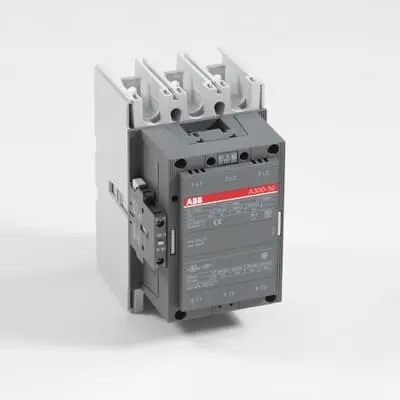
Block Contactor 1SFL557063R7211 is a DC-operated switchgear device for 3-phase railway applications, delivering reliable control via 20–60 V DC coils. Rail and industrial projects demand devices that withstand vibration, minimize unscheduled downtime, and simplify routine maintenance in confined cabinet spaces. It carries critical certifications including IEC/EN 60947-1 and IEC/EN 60947-4-1, UL 60947-4-1, and EN 50155 railway approvals to support safety compliance in rail environments. By design, it supports high-current AC-1/AC-3 duties with 3P poles and integrated auxiliary contacts, enhancing control schemes. This makes it a robust choice for system integrators seeking dependable performance with straightforward installation and long-term total cost of ownership improvements.
Product Information
Extended Description
1SFL557063R7211 ABB: A 3-phase Contactor suitable for Rail way applications application. Operated with a wide voltage control voltage range 20-60 V, DC
Minimum Order Quantity
1 piece
Customs Tariff Number
85364900
Replacement Product ID (NEW)
1SFL587063R1122
Data Sheet, Technical Information
1SBC100192C0206
Instructions and Manuals
Contactors A145, A185, A210, A260, A300
Dimension Diagram
53540930-2
Product Net Width
140 mm
Product Net Depth / Length
180.5 mm
Product Net Height
227 mm
Product Net Weight
5.5 kg
Number of Main Contacts NO
3
Number of Main Contacts NC
0
Number of Auxiliary Contacts NO
1
Number of Auxiliary Contacts NC
1
Number of Poles
3P
Standards
IEC/EN 60947-1, IEC/EN 60947-4-1, UL 60947-4-1, CSA C22.2 No. 60947-4-1, IEC 60077-1 (applicable parts), IEC 60077-2 (applicable parts), EN 50155 (applicable parts), TR CU 001/2011, IEC 61373, For compliance confirmation on applicable parts based on your application and combination, please consult your ABB sales representatives.
Rated Operational Voltage
Main Circuit 690 V
Conventional Free-air Thermal Current (Ith)
acc. to IEC 60947-4-1, Open Contactors Θ = 40 °C 500 A
Rated Operational Current AC-1 (Ie)
(690 V) 40 °C 500 A | (690 V) 55 °C 400 A | (690 V) 70 °C 325 A
Rated Operational Current AC-3 (Ie)
(415 V) 55 °C 300 A | (440 V) 55 °C 280 A | (500 V) 55 °C 280 A | (690 V) 55 °C 280 A | (380 / 400 V) 55 °C 305 A | (220 / 230 / 240 V) 55 °C 305
Rated Operational Current DC-1 (Ie)
(110 V) 2 Poles in Series, 40 °C 450 A | (220 V) 3 Poles in Series, 40 °C 450 A
Rated Operational Current DC-3 (Ie)
(110 V) 2 Poles in Series, 40 °C 450 A | (220 V) 3 Poles in Series, 40 °C 450 A
Rated Operational Current DC-5 (Ie)
(110 V) 2 Poles in Series, 40 °C 450 A | (220 V) 3 Poles in Series, 40 °C 450 A
Rated Operational Power AC-3 (Pe)
(415 V) 160 kW | (440 V) 160 kW | (500 V) 200 kW | (690 V) 250 kW | (380 / 400 V) 160 kW | (220 / 230 / 240 V) 90 kW
Rated Breaking Capacity AC-3
8 x Ie AC-3
Rated Making Capacity AC-3
10 x Ie AC-3
Short-Circuit Protective Devices
gG Type Fuses 500 A
Rated Short-time Withstand Current Low Voltage (Icw)
at 40 °C Ambient Temp, in Free Air, from a Cold State 10 s 2400 A | at 40 °C Ambient Temp, in Free Air, from a Cold State 15 min 500 A | at 40 °C Ambient Temp, in Free Air, from a Cold State 1 min 1100 A | at 40 °C Ambient Temp, in Free Air, from a Cold State 1 s 3500 A | at 40 °C Ambient Temp, in Free Air, from a Cold State 30 s 1500 A
Maximum Breaking Capacity
cos phi=0.45 (cos phi=0.35 for Ie > 100 A) at 440 V 3000 A | cos phi=0.45 (cos phi=0.35 for Ie > 100 A) at 690 V 2500 A
Rated Insulation Voltage (Ui)
acc. to IEC 60947-4-1 and VDE 0110 (Gr. C) 1000 V | acc. to UL/CSA 600 V
Rated Impulse Withstand Voltage (Uimp)
Main Circuit 8 kV
Maximum Electrical Switching Frequency
(AC-1) 300 cycles per hour | (AC-2 / AC-4) 150 cycles per hour | (AC-3) 300 cycles per hour
Mechanical Durability
5 million
Maximum Mechanical Switching Frequency
300 cycles per hour
Coil Operating Limits
(acc. to IEC 60947-4-1) 0.85 x Uc Min. ... 1.1 x Uc Max. (at θ ≤ 70 °C)
Rated Control Circuit Voltage (Uc)
DC Operation 20 ... 60 V
Coil Consumption
Holding at Max. Rated Control Circuit Voltage 50 Hz 10 V·A | Holding at Max. Rated Control Circuit Voltage 60 Hz 10 V·A | Holding at Max. Rated Control Circuit Voltage DC 2 W | Pull-in at Max. Rated Control Circuit Voltage 50 Hz 470 V·A | Pull-in at Max. Rated Control Circuit Voltage 60 Hz 470 V·A | Pull-in at Max. Rated Control Circuit Voltage DC 520 W
Power Loss
at Rated Operating Conditions per Pole 18 W
Operate Time
Between Coil De-energization and NC Contact Closing 40 ... 50 ms | Between Coil De-energization and NO Contact Opening 43 ... 53 ms | Between Coil Energization and NC Contact Opening 45 ... 85 ms | Between Coil Energization and NO Contact Closing 50 ... 90 ms
Connecting Capacity Main Circuit
Bar 32 mm² | Rigid Al-Cable 2 x 95 ... 120 mm² | Rigid Cu-Cable 16 ... 240 mm²
Connecting Capacity Auxiliary Circuit
Flexible with Ferrule 2x 0.75 ... 2.5 mm² | Flexible with Insulated Ferrule 1x 0.75 ... 2.5 mm² | Flexible 1x0.75 ... 2.5 mm² | Solid 2 x 1 ... 4 mm² | Stranded 1 x 1 .... 4 mm²
Connecting Capacity
Bar 32 mm² | Rigid Al-Cable 120 ... 240 mm² | Rigid Cu-Cable 16 ... 240 mm²
Degree of Protection
acc. to IEC 60529, IEC 60947-1, EN 60529 Coil Terminals IP20 | acc. to IEC 60529, IEC 60947-1, EN 60529 Main Terminals IP00
Connecting Terminals (delivered in open position) Main Poles
Flat type c/w screws and bolts
Tightening Torque
Main Circuit 28 N·m
Terminal Type
Main Circuit: Bars
Product Name
Block Contactor
Maximum Operating Voltage UL/CSA
Main Circuit 600 V
General Use Rating UL/CSA
(600 V AC) 400 A
Horsepower Rating UL/CSA
(200 V AC) Three Phase 100 hp | (208 V AC) Three Phase 100 hp | (220 ... 240 V AC) Three Phase 100 hp | (440 ... 480 V AC) Three Phase 250 hp | (550 ... 600 V AC) Three Phase 300 hp
Full Load Amps Motor Use
(440 ... 480 V AC) Three Phase 302 A | (550 ... 600 V AC) Three Phase 289 A
Ambient Air Temperature
Close to Contactor Fitted with Thermal O/L Relay (0.85 ... 1.1 Uc) -25 ... 50 °C | Close to Contactor without Thermal O/L Relay (0.85 ... 1.1 Uc) -40 ... 70 °C | Close to Contactor for Storage -40 ... 70 °C
Maximum Operating Altitude Permissible
Without Derating 3000 m
Resistance to Shock acc. to IEC 60068-2-27
Shock Direction: A 5 g | Shock Direction: B1 5 g | Shock Direction: B2 5 g | Shock Direction: C1 5 g | Shock Direction: C2 5 g
RoHS Information
CE Declaration of Conformity - Contactor - A(F)95...A(F)300, AM110...AM300, UA95...UA110, (T)AE95....(T)AE110
RoHS Status
Following EU Directive 2011/65/EU
WEEE B2C / B2B
Business To Business
WEEE Category
5. Small Equipment (No External Dimension More Than 50 cm)
BV Certificate
13409/C0 BV
CB Certificate
SE-69480
CQC Certificate
CQC Certificate, Contactor, AF210, AF210B…RT, AF260, AF260B…RT, AF300, AF300B…RT, Made in Sweden
Declaration of Conformity - CCC
CCC Declaration of Conformity, Contactor, AF210, AF210B…RT, AF260, AF260B…RT, AF300, AF300B…RT, Made in Sweden
Declaration of Conformity - CE
CE Declaration of Conformity - Contactor - A(F)95...A(F)300, AM110...AM300, UA95...UA110, (T)AE95....(T)AE110
EAC Certificate
9AKK107046A8618
GL Certificate
GL_20262-04HH
LOVAG Certificate
SE-0115200
LR Certificate
LR_04-00015-E1
RINA Certificate
ELE060313XG/002
RMRS Certificate
RMRS_12-03683-315
Package Level 1 Units
box 1 piece
Package Level 1 Width
203 mm
Package Level 1 Depth / Length
245 mm
Package Level 1 Height
188 mm
Package Level 1 Gross Weight
6.2 kg
Package Level 1 EAN
7320500258484
Object Classification Code
Q
ETIM 7
EC000066 - Power contactor, AC switching
ETIM 8
EC000066 - Power contactor, AC switching
ETIM 9
EC000066 - Power contactor, AC switching
eClass
V11.0 : 27371003
UNSPSC
39121529
IDEA Granular Category Code (IGCC)
4755 >> Contactors
Feature: Wide DC control voltage range 20–60 V. Benefit: Reduces stocking and wiring complexity across PLC outputs and field devices, enabling quicker deployments in refurbished or multi-volt systems. Application: Rail signaling cabinets and traction panels where coil voltage may vary from site to site. Feature: Three main normally open contacts plus one NO and one NC auxiliary contact. Benefit: Simplified control logic and feedback for interlocks, enabling compact, reliable control of three-phase motors. Application: Drive and conveyor systems in rail yards. Feature: High main circuit voltage up to 690 V and rated duty for AC-3 and DC-3. Benefit: Supports demanding braking and starting loads with predictable thermal performance, lowering downtime. Application: Locomotive braking circuits and power conversion stages. Feature: Mechanical durability of 5 million cycles and defined switching frequencies. Benefit: Long service life and reduced maintenance cycles, lowering life-cycle costs. Application: Repeated start/stop cycles in rolling stock and industrial drives. Feature: Robust protection and connection options (IP20 coil, IP00 main; Bar connections up to 32 mm²; flexible cables 0.75–2.5 mm²). Benefit: Easier, faster installation with reliable terminations and safer operation in enclosures. Application: Panel mounting in tight spaces and retrofit projects. Feature: Compliance with IEC/EN standards and EN 50155 railway requirements. Benefit: Regulatory peace of mind and smoother asset audits. Application: Systems requiring rail-grade certification for safety and performance.
Get a Quick Quote for a ABB 1SFL557063R7211
Chat with us on WhatsApp - fast responses guaranteed
Need to speak with someone? We'll call you back within 2 hours during business hours
Interested in ABB 1SFL557063R7211?
Enquire Now
FAQs
For proper installation, ensure the main circuit uses bar or rigid copper/aluminum conductors within the 32 mm² to 240 mm² range and connect auxiliaries with flexible or solid conductors in the 0.75–4 mm² range. The device should be mounted in a ventilated enclosure, with coil terminals protected to IP20 and main terminals to IP00. Maintain clearances per ABB installation sheets and observe the 28 N·m tightening torque on main terminals.
The contactor features a main circuit rated up to 690 V and 3 NO main contacts with 1 NO and 1 NC auxiliary contact. AC-1 ratings reach up to 500 A at 690 V, while AC-3 ratings vary by voltage (e.g., 300 A at 415 V, 280 A at 690 V). DC-1 and DC-3 ratings provide solutions for low-voltage control of larger field loads. Short-time withstand and breaking capacities support reliable fault clearing in rail systems.
Yes. It is designed for rail environments with railway-focused certifications including EN 50155 applicability and adherence to IEC/EN 60947-1 and IEC/EN 60947-4-1. The device supports robust operation under vibration, wide temperature ranges, and standard IEC/UL safety standards, making it suitable for signaling panels, traction drives, and other rail control applications.
Key certifications include IEC/EN 60947-1 and IEC/EN 60947-4-1, UL 60947-4-1/CSA, EN 50155 for railway equipment, and various declarations of conformity such as CE. Additional approvals like BV, GL, LR, RINA, and EAC are documented in the data package. When selecting, reference the official datasheet 1SBC100192C0206 for complete certification mapping.
Replacement Part ID is 1SFL587063R1122, allowing seamless model-to-model substitutions. Maintenance resources include the Data Sheet 1SBC100192C0206 and the Dimension Diagram 53540930-2, plus manuals referencing Contactors A145, A185, A210, A260, A300. These resources support field service, spare parts planning, and safe reconfiguration in retrofit projects for rail and industrial installations.