ABB 1SFL587002R4211 Block Contactor - UL/CSA
Part Number: 1SFL587002R4211
Quick Summary
ABB 1SFL587002R4211 Block Contactor is a 3-pole switching device designed to control motors up to 160 kW at 400 V AC in industrial automation. Operators often confront panel heat, energy waste, and inconsistent performance in unstable networks; AF technology in this model addresses those challenges with faster operation and built-in surge protection. The unit supports a control voltage of 110–120 V at 50/60 Hz, and it is designed for easy expansion with auxiliary contact blocks and a broad range of accessories. CE and UL/CSA certifications, along with RoHS and UKCA considerations, ensure global compliance. By combining compact form with robust protection, it delivers reliability, energy efficiency, and reduced maintenance costs for motor control centers and line start applications.
Product Information
Extended Description
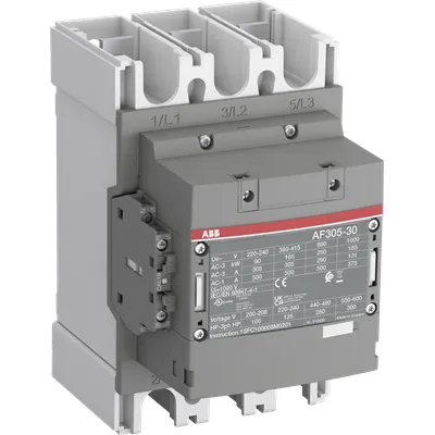
1SFL587002R4211 ABB: The AF305-30-11-42 is a 3 pole - 1000 V IEC or 600 V UL contactor with Main Circuit Bars, controlling motors up to 160 kW / 400 V AC (AC-3) or 250 hp / 480 V UL and switching power circuits up to 500 A (AC-1) or 400 A UL general use. Thanks to the AF technology, the contactor has a control voltage range (110-120 V 50/60 Hz),faster operation time, reducing panel energy consumptions and ensuring distinct operations in unstable networks. Furthermore, surge protection is built-in, offering a compact solution. AF contactors have a block type design, can be easily extended with add-on auxiliary contact blocks and an additional wide range of accessories.
Minimum Order Quantity
1 piece
Customs Tariff Number
8536490099
Data Sheet, Technical Information
1SBC100214C0202 - Main catalog Motor protection and control Manual motor starters, contactors and overload relays (PDF) - Edition 2024
Data Sheet, Technical Information (Part 2)
Contactors and Overload relays guide
Instructions and Manuals
Operating instruction, Contactor, AF(S)190 ... AF(S)370
CAD Dimensional Drawing
Information - 2D and 3D files for CAD systems
Product Net Width
140 mm
Product Net Depth / Length
180 mm
Product Net Height
225 mm
Product Net Weight
3.9 kg
Number of Main Contacts NO
3
Number of Main Contacts NC
0
Number of Auxiliary Contacts NO
1
Number of Auxiliary Contacts NC
1
Number of Poles
3P
Rated Operational Voltage
Main Circuit 1000 V
Rated Frequency (f)
Main Circuit 50 / 60 Hz
Conventional Free-air Thermal Current (Ith)
acc. to IEC 60947-4-1, Open Contactors Θ = 40 °C 500 A
Rated Operational Current AC-1 (Ie)
(1000 V) 40 °C 375 A | (1000 V) 60 °C 325 A | (1000 V) 70 °C 260 A | (690 V) 40 °C 500 A | (690 V) 60 °C 400 A | (690 V) 70 °C 325 A
Rated Operational Current AC-3 (Ie)
(415 V) 60 °C 305 A | (440 V) 60 °C 305 A | (500 V) 60 °C 290 A | (690 V) 60 °C 290 A | (1000 V) 60 °C 131 A | (380 / 400 V) 60 °C 305 A | (220 / 230 / 240 V) 60 °C 305 A
Rated Operational Power AC-3 (Pe)
(415 V) 160 kW | (440 V) 160 kW | (500 V) 200 kW | (690 V) 250 kW | (1000 V) 185 kW | (380 / 400 V) 160 kW | (220 / 230 / 240 V) 90 kW
Rated Breaking Capacity AC-3
8 x Ie AC-3
Rated Making Capacity AC-3
10 x Ie AC-3
Rated Short-time Withstand Current Low Voltage (Icw)
at 40 °C Ambient Temp, in Free Air, from a Cold State 10 s 2440 A | at 40 °C Ambient Temp, in Free Air, from a Cold State 15 min 500 A | at 40 °C Ambient Temp, in Free Air, from a Cold State 1 min 996 A | at 40 °C Ambient Temp, in Free Air, from a Cold State 1 s 3050 A | at 40 °C Ambient Temp, in Free Air, from a Cold State 30 s 1409 A
Maximum Breaking Capacity
cos phi=0.45 (cos phi=0.35 for Ie > 100 A) at 440 V 4600 A | cos phi=0.45 (cos phi=0.35 for Ie > 100 A) at 690 V 3800 A
Rated Insulation Voltage (Ui)
acc. to IEC 60947-4-1 and VDE 0110 (Gr. C) 1000 V | acc. to UL/CSA 1000 V
Rated Impulse Withstand Voltage (Uimp)
Main Circuit 8 kV
Maximum Electrical Switching Frequency
(AC-1) 300 cycles per hour | (AC-2 / AC-4) 150 cycles per hour | (AC-3) 300 cycles per hour
Mechanical Durability
5 million
Maximum Mechanical Switching Frequency
300 cycles per hour
Rated Control Circuit Voltage (Uc)
50 Hz 110 ... 120 V | 60 Hz 110 ... 120 V
Coil Consumption
Holding at Max. Rated Control Circuit Voltage 50 Hz 17 V·A | Holding at Max. Rated Control Circuit Voltage 50 Hz 3 W | Holding at Max. Rated Control Circuit Voltage 60 Hz 17 V·A | Holding at Max. Rated Control Circuit Voltage 60 Hz 3 W | Pull-in at Max. Rated Control Circuit Voltage 50 Hz 340 V·A | Pull-in at Max. Rated Control Circuit Voltage 60 Hz 340 V·A
Power Loss
at Rated Operating Conditions AC-1 per Pole 50 W | at Rated Operating Conditions AC-3 per Pole 19 W
Operate Time
Between Coil De-energization and NO Contact Opening 20 ... 30 ms | Between Coil Energization and NO Contact Closing 20 ... 35 ms
Connecting Capacity Auxiliary Circuit
Flexible with Ferrule 1x 0.75 ... 2.5 mm² | Flexible with Ferrule 2x 0.75 ... 2.5 mm² | Flexible with Insulated Ferrule 1x 0.75 ... 2.5 mm² | Flexible with Insulated Ferrule 2x 0.75 ... 2.5 mm² | Flexible 1x 0.75 ... 2.5 mm² | Flexible 2x 0.75 ... 2.5 mm² | Solid 1x 1 ... 4 mm² | Solid 2x 1 ... 4 mm² | Stranded 1x 1 ... 4 mm² | Stranded 2x 1 ... 4 mm²
Connecting Capacity
Flexible 2 x 70 ... 185 mm² | Rigid Al-Cable 1 x 185 ... 240 mm² | Rigid Cu-Cable 2 x 70 ... 185 mm²
Wire Stripping Length
Auxiliary Circuit 9 mm | Control Circuit 9 mm
Degree of Protection
acc. to IEC 60529, IEC 60947-1, EN 60529 Coil Terminals IP20 | acc. to IEC 60529, IEC 60947-1, EN 60529 Main Terminals IP00
Recommended Screw Driver
Main Circuit M10 | Control Circuit M3.5
Tightening Torque
Auxiliary Circuit 1 N·m | Cable Lug 28 N·m | Control Circuit 1 N·m | Main Circuit 22 ... 43 N·m
Terminal Type
Main Circuit: Bars
Product Name
Block Contactor
Maximum Operating Voltage UL/CSA
Main Circuit 1000 V
General Use Rating UL/CSA
(1000 V AC) 400 A
Horsepower Rating UL/CSA
(200 ... 208 V AC) Three Phase 100 hp | (220 ... 240 V AC) Three Phase 125 hp | (440 ... 480 V AC) Three Phase 250 hp | (550 ... 600 V AC) Three Phase 300 hp
Tightening Torque UL/CSA
Auxiliary Circuit 9 in·lb | Control Circuit 9 in·lb | Main Circuit 372 in·lb
Full Load Amps Motor Use
(200 ... 208 V AC) Three Phase 285 A | (220 ... 240 V AC) Three Phase 312 A | (440 ... 480 V AC) Three Phase 302 A | (550 ... 600 V AC) Three Phase 289 A
Ambient Air Temperature
Close to Contactor Fitted with Thermal O/L Relay (0.85 ... 1.1 Uc) -25 ... 55 °C | Close to Contactor without Thermal O/L Relay (0.85 ... 1.1 Uc) -40 ... 70 °C | Close to Contactor for Storage -40 ... 70 °C
Maximum Operating Altitude Permissible
Without Derating 3000 m
Conflict Minerals Reporting Template (CMRT)
CMRT - Conflict Minerals Reporting Template
REACH Declaration
REACH - Letter of Confirmation for block contactors, contactor relays, installation contactors, mini contactors, mini contactor relays, thermal overload relays, electronic overload relays and related accessories
RoHS Information
RoHS II declaration for block contactors, installation contactors, mini contactors, mini contactor relays, thermal overload relays, electronic overload relays and related accessories
RoHS Status
Following EU Directive 2011/65/EU and Amendment 2015/863 July 22, 2019
Toxic Substances Control Act - TSCA
Toxic Substances Control Act (TSCA) declaration for Contactors
WEEE B2C / B2B
Business To Business
WEEE Category
5. Small Equipment (No External Dimension More Than 50 cm)
ABB EcoSolutions
Yes
ABB Site Meeting Group Waste To Landfill Target
Non-hazardous waste is sent to a landfill, where there is no alternative option available within 100km of a facility
End Of Life Disassembling Instructions
End-of-life instruction - AF(S)265(B)-**(RT) to AF(S)370(B)-**(RT)
Environmental Product Declaration - EPD
Environmental Product Declaration, Contactors, AF(S)265-AF(S)370 (SE)
Improved Energy Efficiency for Customers
Product Efficiency - Product considered more energy-efficient compared to similar product on market or older products from the same line
Recyclability Rate of the Product acc. to EN45555
Design for Closing Resource Loops - Standard EN45555 - 76.3 %
Sustainable Material Content in Product (wt. %)
Recycled Metal - 33 %
A2L Certificate – UL
UL Certificate of Compliance A2L, Contactor, AF190 - AF370
Declaration of Conformity - CE
CE Declaration of Conformity - Contactor - AF116...AF370
Declaration of Conformity - UKCA
UK Declaration of Conformity - Contactors >100A
UL Certificate
cULus Certificate, Contactor, AF265, AF305, AF370, AX260, AX300, AX370, AFS265, AFS305, AFS370
Package Level 1 Units
box 1 piece
Package Level 1 Width
263 mm
Package Level 1 Depth / Length
203 mm
Package Level 1 Height
289 mm
Package Level 1 Gross Weight
4.6 kg
Package Level 1 EAN
7320500561119
Object Classification Code
Q
ETIM 7
EC000066 - Power contactor, AC switching
ETIM 8
EC000066 - Power contactor, AC switching
ETIM 9
EC000066 - Power contactor, AC switching
eClass
V11.0 : 27371003
UNSPSC
39121529
IDEA Granular Category Code (IGCC)
4758 >> Iec Contactors
AF technology enables faster coil operation and reduced panel energy consumption, delivering quicker start/stop sequences and lower thermal stress in conveyors and pumps. This translates to measurable improvements in line throughput and energy efficiency, especially in high-cycle applications where every millisecond and watt matters. Built‑in surge protection protects upstream power quality, reducing nuisance trips and extending contactor life in networks with voltage spikes. The 3-pole main circuit rated for up to 1000 V supports diverse voltages and frequencies, enabling scalable motor control for pumps, fans, and compressors. The block-type design is modular and extendable with auxiliary contact blocks, allowing seamless signaling and interlocking without rewiring. Compatibility with CAD resources and installation manuals accelerates commissioning and minimizes field mistakes. Compact footprint plus IP20/IP00 considerations simplify panel layout and maintenance accessibility, reducing space, time, and labor costs. Energy loss is minimized with 50 W per pole (AC-1) and 19 W per pole (AC-3), contributing to lower operating expenses over the motor’s life.
Get a Quick Quote for a ABB 1SFL587002R4211
Chat with us on WhatsApp - fast responses guaranteed
Need to speak with someone? We'll call you back within 2 hours during business hours
Interested in ABB 1SFL587002R4211?
Enquire Now
FAQs
Install as a 3-pole main circuit device with bars, using the recommended tightening torque for the main circuit 22–43 N·m. Use flexible conductors 2x 70–185 mm² or rigid conductors 185–240 mm² for the main connections, and ensure auxiliary wiring follows the 9 mm wire stripping guidance. The unit supports a 110–120 V coil at 50/60 Hz and can be extended with add-on auxiliary contact blocks to suit signaling needs.
AC-1 rated current at 1000 V is up to 375 A (40 °C) and 325 A (60 °C), decreasing with temperature. For AC-3, Ie values include 305 A at 415/440 V, 290 A at 500/690 V, and 131 A at 1000 V. Rated AC-3 power reaches up to 250 kW at 690 V and down to 185 kW at 1000 V. These ratings support reliable motor starting and control in diverse industrial configurations.
Yes. At 380–400 V and 60 °C, the device provides AC-3 ratings around 305 A with up to 160 kW of controlled power, and at 440–480 V it maintains robust performance for heavy-duty applications. The 1000 V main circuit rating also supports versatile operation across mixed-voltage systems commonly found in large industrial facilities.
The unit carries CE and UKCA declarations, UL/CSA listings, and RoHS compliance. These certifications verify safety, electromagnetic compatibility, environmental compliance, and suitability for global deployment. For panel builders and end users, this means streamlined procurement, easier regulatory approvals, and assurance that the contactor meets international standards for motor control in critical processes.
Expect reduced downtime and energy costs thanks to built‑in surge protection, faster switching, and efficient coil management. Mechanical durability is rated at about 5 million cycles, while power loss is reduced to 50 W per pole (AC-1) and 19 W per pole (AC-3). The modular design with add-on auxiliary blocks lowers wiring complexity and service time, contributing to a favorable total cost of ownership over the motor’s life.