ABB 1SFL597001R7111 Block Contactor - 1000V/700A
Part Number: 1SFL597001R7111
Quick Summary
ABB 1SFL597001R7111 block contactor controls motors and power circuits in industrial equipment. Its wide control voltage range tolerates voltage variations, reducing panel energy waste. Designed for industrial automation, it supports motors up to 250 kW and keeps switching power circuits under 700 A. CE labeling ensures safety compliance across European installations, while UL/CSA listings validate North American usage. With IP-rated coil terminals and IP00 main terminals, installation and maintenance remain straightforward in control cabinets. This product aligns with ABB EcoSolutions goals, delivering energy efficiency, recyclability, and lifecycle cost reductions through durable design and modular expansion. This combination supports faster commissioning and reduces downtime by simplifying wiring and diagnostics, which engineers and procurement teams appreciate in large-scale automation projects.
Product Information
Extended Description
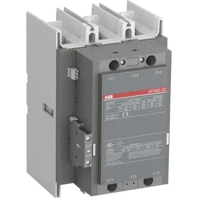
1SFL597001R7111 ABB: The AF460-30-11-71 is a 3 pole - 1000 V IEC or 600 V UL contactor with pre-mounted auxiliary contacts and Main Circuit Bars, controlling motors up to 250 kW / 400 V AC (AC-3) or 400 hp / 480 V UL and switching power circuits up to 700 A (AC-1) or 650 A UL general use. Thanks to the AF technology, the contactor has a wide control voltage range (250-500 V 50/60 Hz and DC), managing large control voltage variations, reducing panel energy consumptions and ensuring distinct operations in unstable networks. Furthermore, surge protection is built-in, offering a compact solution. AF contactors have a block type design, can be easily extended with add-on auxiliary contact blocks and an additional wide range of accessories.
Minimum Order Quantity
1 piece
Customs Tariff Number
85364900
Data Sheet, Technical Information
1SBC100214C0202 - Main catalog Motor protection and control Manual motor starters, contactors and overload relays (PDF) - Edition 2024
Data Sheet, Technical Information (Part 2)
Contactors and Overload relays guide
Instructions and Manuals
1SFC380023-en
CAD Dimensional Drawing
Information - 2D and 3D files for CAD systems
Dimension Diagram
53540919-59
Product Net Width
186 mm
Product Net Depth / Length
216 mm
Product Net Height
278 mm
Product Net Weight
10.6 kg
Number of Main Contacts NO
3
Number of Main Contacts NC
0
Number of Auxiliary Contacts NO
1
Number of Auxiliary Contacts NC
1
Number of Poles
3P
Rated Operational Voltage
Main Circuit 1000 V
Rated Frequency (f)
Main Circuit 50 / 60 Hz
Conventional Free-air Thermal Current (Ith)
acc. to IEC 60947-4-1, Open Contactors Θ = 40 °C 700 A
Rated Operational Current AC-1 (Ie)
(1000 V) 40 °C 700 A | (1000 V) 55 °C 600 A | (1000 V) 60 °C 600 A | (1000 V) 70 °C 480 A | (690 V) 40 °C 700 A | (690 V) 55 °C 600 A | (690 V) 70 °C 480 A
Rated Operational Current AC-3 (Ie)
(415 V) 55 °C 460 A | (440 V) 55 °C 460 A | (500 V) 55 °C 460 A | (690 V) 55 °C 400 A | (1000 V) 55 °C 200 A | (380 / 400 V) 55 °C 460 A | (220 / 230 / 240 V) 55 °C 460 A
Rated Operational Current DC-1 (Ie)
(110 V) 1-Pole, 40 °C 700 A | (110 V) 2 Poles in Series, 40 °C 700 A | (220 V) 3 Poles in Series, 40 °C 700 A | (600 V) 3 Poles in Series, 40 °C 700 A
Rated Operational Current DC-3 (Ie)
(110 V) 1-Pole, 40 °C 700 A | (110 V) 2 Poles in Series, 40 °C 700 A | (220 V) 3 Poles in Series, 40 °C 700 A | (600 V) 3 Poles in Series, 40 °C 700 A
Rated Operational Current DC-5 (Ie)
(110 V) 1-Pole, 40 °C 700 A | (110 V) 2 Poles in Series, 40 °C 700 A | (220 V) 3 Poles in Series, 40 °C 700 A | (600 V) 3 Poles in Series, 40 °C 700 A
Rated Operational Power AC-3 (Pe)
(415 V) 250 kW | (440 V) 250 kW | (500 V) 315 kW | (690 V) 355 kW | (1000 V) 280 kW | (380 / 400 V) 250 kW | (220 / 230 / 240 V) 132 kW
Rated Breaking Capacity AC-3
8 x Ie AC-3
Rated Making Capacity AC-3
10 x Ie AC-3
Short-Circuit Protective Devices
gG Type Fuses 1.5 ... 1.8 In A
Rated Short-time Withstand Current Low Voltage (Icw)
at 40 °C Ambient Temp, in Free Air, from a Cold State 10 s 4400 A | at 40 °C Ambient Temp, in Free Air, from a Cold State 15 min 840 A | at 40 °C Ambient Temp, in Free Air, from a Cold State 1 min 2500 A | at 40 °C Ambient Temp, in Free Air, from a Cold State 1 s 4600 A | at 40 °C Ambient Temp, in Free Air, from a Cold State 30 s 3100 A
Maximum Breaking Capacity
cos phi=0.45 (cos phi=0.35 for Ie > 100 A) at 440 V 5000 A | cos phi=0.45 (cos phi=0.35 for Ie > 100 A) at 690 V 4500 A
Rated Insulation Voltage (Ui)
acc. to IEC 60947-4-1 and VDE 0110 (Gr. C) 1000 V | acc. to UL/CSA 600 V
Rated Impulse Withstand Voltage (Uimp)
Main Circuit 8 kV
Maximum Electrical Switching Frequency
(AC-1) 300 cycles per hour | (AC-2 / AC-4) 60 cycles per hour | (AC-3) 300 cycles per hour
Mechanical Durability
3 million
Maximum Mechanical Switching Frequency
300 cycles per hour
Coil Operating Limits
(acc. to IEC 60947-4-1) 0.85 x Uc Min. ... 1.1 x Uc Max. (at θ ≤ 70 °C)
Rated Control Circuit Voltage (Uc)
50 Hz 250 ... 500 V | 60 Hz 250 ... 500 V | DC Operation 250 ... 500 V
Coil Consumption
Holding at Max. Rated Control Circuit Voltage 50 Hz 12 V·A | Holding at Max. Rated Control Circuit Voltage 60 Hz 12 V·A | Holding at Max. Rated Control Circuit Voltage DC 7.5 V·A | Pull-in at Max. Rated Control Circuit Voltage 50 Hz 950 V·A | Pull-in at Max. Rated Control Circuit Voltage 60 Hz 950 V·A | Pull-in at Max. Rated Control Circuit Voltage DC 885 V·A
Power Loss
at Rated Operating Conditions per Pole 21 W
Operate Time
Between Coil De-energization and NC Contact Closing 45 ... 55 ms | Between Coil De-energization and NO Contact Opening 48 ... 58 ms | Between Coil Energization and NC Contact Opening 45 ... 115 ms | Between Coil Energization and NO Contact Closing 50 ... 120 ms
Connecting Capacity Main Circuit
Bar 47 mm² | Rigid Al-Cable 2x240 mm² | Rigid Cu-Cable 240 mm²
Connecting Capacity Auxiliary Circuit
Flexible with Ferrule 2x 0.75 ... 2.5 mm² | Flexible with Insulated Ferrule 1x 0.75 ... 2.5 mm² | Flexible 2x0.75 ... 2.5 mm² | Solid 2 x 1 ... 4 mm² | Stranded 2 x 1 .... 4 mm²
Connecting Capacity
Bar 47 mm² | Rigid Al-Cable 2x240 mm² | Rigid Cu-Cable 240 mm²
Degree of Protection
acc. to IEC 60529, IEC 60947-1, EN 60529 Coil Terminals IP20 | acc. to IEC 60529, IEC 60947-1, EN 60529 Main Terminals IP00
Tightening Torque
Cable Lug 35 N·m | Main Circuit 35 N·m
Terminal Type
Main Circuit: Bars
Product Name
Block Contactor
NEMA Size
6
Horsepower Rating NEMA
(200 V AC) Three Phase 150 Hp | (230 V AC) Three Phase 200 Hp | (460 V AC) Three Phase 400 Hp | (575 V AC) Three Phase 400 Hp
Maximum Operating Voltage UL/CSA
Main Circuit 1000 V
General Use Rating UL/CSA
(1000 V AC) 650 A
Horsepower Rating UL/CSA
(200 V AC) Three Phase 150 hp | (208 V AC) Three Phase 150 hp | (220 ... 240 V AC) Three Phase 200 hp | (440 ... 480 V AC) Three Phase 400 hp | (550 ... 600 V AC) Three Phase 500 hp
Full Load Amps Motor Use
(440 ... 480 V AC) Three Phase 477 A | (550 ... 600 V AC) Three Phase 472 A
Ambient Air Temperature
Close to Contactor Fitted with Thermal O/L Relay (0.85 ... 1.1 Uc) -25 ... 50 °C | Close to Contactor without Thermal O/L Relay (0.85 ... 1.1 Uc) -40 ... 70 °C | Close to Contactor for Storage -40 ... 70 °C
Maximum Operating Altitude Permissible
Without Derating 3000 m
Resistance to Shock acc. to IEC 60068-2-27
Shock Direction: A 5 g | Shock Direction: B1 5 g | Shock Direction: B2 5 g | Shock Direction: C1 5 g | Shock Direction: C2 5 g
Conflict Minerals Reporting Template (CMRT)
CMRT - Conflict Minerals Reporting Template
REACH Declaration
REACH - Letter of Confirmation for block contactors, contactor relays, installation contactors, mini contactors, mini contactor relays, thermal overload relays, electronic overload relays and related accessories
RoHS Information
RoHS II declaration for block contactors, installation contactors, mini contactors, mini contactor relays, thermal overload relays, electronic overload relays and related accessories
RoHS Status
Following EU Directive 2011/65/EU and Amendment 2015/863 July 22, 2019
Toxic Substances Control Act - TSCA
Toxic Substances Control Act (TSCA) declaration for Contactors
WEEE B2C / B2B
Business To Business
WEEE Category
5. Small Equipment (No External Dimension More Than 50 cm)
ABB EcoSolutions
Yes
ABB Site Meeting Group Waste To Landfill Target
Non-hazardous waste is sent to a landfill, where there is no alternative option available within 100km of a facility
End Of Life Disassembling Instructions
End-of-life instruction - AF(S)400(B)-**;AF(S)460(B)-**;AF460N6
Environmental Product Declaration - EPD
Environmental Product Declaration, Contactors, AF(S)400-AF(S)460 (SE)
Improved Energy Efficiency for Customers
Product Efficiency - Product considered more energy-efficient compared to similar product on market or older products from the same line
Recyclability Rate of the Product acc. to EN45555
Design for Closing Resource Loops - Standard EN45555 - 63.1 %
Sustainable Material Content in Product (wt. %)
Recycled Metal - 37 %
ABS Certificate
ABS Certificate, Contactor, AF400...AF2050 (Sweden)
BV Certificate
BV Certificate, Contactor, AF400 ... AF2850
CB Certificate
SE-82316
CCS Certificate
CCS Certificate, Contactor, AF116 to AF2850 (Sweden)
CQC Certificate
CQC Certificate, AC Contactor, AF400-30-*-*,AF460-30-*-*,AFS400-30-*-*, AFS460-30-*-*, Made in Sweden | CQC Certificate, Contactor, AF400, AF460, Made in China
CSA Certificate
306711
Declaration of Conformity - CCC
CCC Declaration of Conformity, AC Contactor, AF400-30-*-*,AF460-30-*-*,AFS400-30-*-*, AFS460-30-*-*, Made in Sweden | CCC Declaration of Conformity, Contactor, AF400, AF460, Made in China
Declaration of Conformity - CE
CE Declaration of Conformity - Contactor - AF400...AF2850
Declaration of Conformity - UKCA
UK Declaration of Conformity - Contactors >100A
DNV Certificate
DNV_E-10966
DNV GL Certificate
DNV Certificate, Contactor, AF400...AF2850
EAC Certificate
9AKK107046A8618
GL Certificate
GL_42988-02HH
LOVAG Certificate
FI103
LR Certificate
Lloyds register Certificate, Contactor, AF400...AF2850
PRS Certificate
PRS Certificate - AF116...AF1650
RINA Certificate
RINA Certificate, AF95, AF110, AF145, AF185, AF210, AF260, AF300, AF400, AF460, AF580, AF750, AF1250, AF1350, AF1650, AF2050, AF2650, AF116, AF140, AF146, AF190, AF205, AF265, AF305, AF370
RMRS Certificate
9AKK107045A6978
UL Certificate
cULus Certificate, Contactor, AF400, AF460, AFS400, AFS460
UL Listing Card
UL_E36588
Package Level 1 Units
box 1 piece
Package Level 1 Width
280 mm
Package Level 1 Depth / Length
375 mm
Package Level 1 Height
310 mm
Package Level 1 Gross Weight
12 kg
Package Level 1 EAN
7320500249994
Object Classification Code
Q
ETIM 7
EC000066 - Power contactor, AC switching
ETIM 8
EC000066 - Power contactor, AC switching
ETIM 9
EC000066 - Power contactor, AC switching
eClass
V11.0 : 27371003
UNSPSC
39121529
IDEA Granular Category Code (IGCC)
4758 >> Iec Contactors
E-Number (Finland)
3709251
E-Number (Norway)
4115293
E-Number (Sweden)
3228345
Feature: AF technology with a wide control voltage range of 250-500 V AC/DC. Business Impact: This tolerance minimizes control voltage sensitivity, reducing energy waste and panel heat, while improving reliability in networks with fluctuating voltages. Application: Ideal for variable-speed drives and systems where supply quality varies across shifts or different sites. Feature: Built-in surge protection and compact AF block design. Business Impact: Enhances reliability, lowers external protection needs, and reduces panel space requirements. Application: Motor control panels in packaging and material-handling lines where surge events are common. Feature: Three main NO contacts plus one NO/NC auxiliary contact. Business Impact: Enables precise interlocking, status feedback, and safe sequencing without additional components. Application: Start/stop logic and monitoring circuits in conveyors and processing equipment. Feature: Pre-mounted auxiliary contacts and expandability with add-on blocks. Business Impact: Simplifies wiring, accelerates commissioning, and enables scalable control architectures over time. Application: Large automation plants that evolve with new safety interlocks or signaling needs. Feature: High-insulation main circuit rating (up to 1000 V) and strong mechanical durability. Business Impact: Supports long service life under demanding loads and reduces maintenance frequency. Application: Heavy machinery and line-start applications in process automation. Feature: Robust connection capabilities (47 mm² main circuit, 2x240 mm² rigid Al, 240 mm² rigid Cu). Business Impact: Allows direct, low-resistance terminations for power circuits, reducing installation costs. Application: Large motor feeders and power distribution in industrial cabinets.
Get a Quick Quote for a ABB 1SFL597001R7111
Chat with us on WhatsApp - fast responses guaranteed
Need to speak with someone? We'll call you back within 2 hours during business hours
Interested in ABB 1SFL597001R7111?
Enquire Now
FAQs
Mounting the ABB 1SFL597001R7111 requires space for a 186 mm wide, 216 mm deep, and 278 mm high unit. It weighs about 10.6 kg and uses main circuit bars up to 47 mm² with rigid Cu- or Al-cable options up to 240 mm². The compact block design accepts add-on auxiliary contact blocks for future expansion while maintaining a clean control cabinet layout.
AC-3 performance is rated at 460 A at 415 V and 400 A at 690 V, with other voltages listed for different installations. The unit supports a main circuit insulation of 1000 V and a maximum breaking capacity around 4500–5000 A cos phi. This makes it suitable for high-inertia motors in process lines and packaging systems.
Yes, the coil supports 250–500 V control voltage (AC, 50/60 Hz) and DC operation. Coil consumption is listed as 12 V·A holding at max rated voltage and 950–885 V·A pull-in values depending on frequency, with typical pull-in and release times. This ensures reliable triggering and stable operation across voltage fluctuations.
CE and UL/CSA certifications are supported, with CE Declaration of Conformity for European installations and UL Listing Card documentation for North American compliance. Additional declarations cover RoHS, REACH, and environmental compliance, while IP ratings ensure safe operation in typical control cabinets. This reduces compliance risk and accelerates project approvals worldwide.
Wiring and terminal options include main circuit connections via bars (47 mm²) or rigid Al-Cable 2x240 mm² and rigid Cu-Cable 240 mm², plus flexible/insulated options for auxiliary circuits 0.75–4 mm². Coil terminals are IP20 protected, while main terminals are IP00. Tightening torque is 35 N·m for reliable, code-compliant connections.