ABB 1SFL637033R7022 Block Contactor - CE UL Certified
Part Number: 1SFL637033R7022
Quick Summary
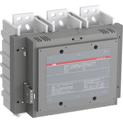
ABB 1SFL637033R7022 Block Contactor is a high-capacity switch for three-pole power loads in industrial systems. In renewable energy and motor-control panels, inconsistent coil voltage and thermal cycling can cause unexpected trips. This ABB unit carries CE, UL, and UKCA certifications for global compliance, ensuring safety in European, UK, and North American deployments. Used in motor protection and industrial automation, it translates into reliable uptime and lower maintenance. Apart from its robust 3P configuration, the device supports 100-250 V control voltage and DC operation, enhancing design flexibility. Its compact footprint and 15 kg weight simplify enclosure layouts, while the 210 x 242 x 283 mm dimensions fit standard racks. With a rated insulation of 1000 V and a main-circuit breaking capacity up to 7500 A, it handles demanding loads with margins.
Product Information
Extended Description
1SFL637033R7022 ABB: A 3-phase Contactor suitable for power generation applications in renewable energy segment up to max 1000 V. Operated with wide control voltage range 100-250 V, AC/DC
Minimum Order Quantity
1 piece
Customs Tariff Number
85364900
Data Sheet, Technical Information
1SBC100214C0202 - Main catalog Motor protection and control Manual motor starters, contactors and overload relays (PDF) - Edition 2024
Data Sheet, Technical Information (Part 2)
Contactors and Overload relays guide
Instructions and Manuals
1SFC380023-en
CAD Dimensional Drawing
Information - 2D and 3D files for CAD systems
Dimension Diagram
53540919-60
Product Net Width
210 mm
Product Net Depth / Length
242 mm
Product Net Height
283 mm
Product Net Weight
13.6 kg
Number of Main Contacts NO
3
Number of Main Contacts NC
0
Number of Auxiliary Contacts NO
2
Number of Auxiliary Contacts NC
2
Number of Poles
3P
Rated Operational Voltage
Main Circuit 1000 V
Rated Frequency (f)
Main Circuit 50 / 60 Hz
Conventional Free-air Thermal Current (Ith)
acc. to IEC 60947-4-1, Open Contactors Θ = 40 °C 1050 A
Rated Operational Current AC-1 (Ie)
(1000 V) 40 °C 1000 A | (1000 V) 55 °C 875 A | (1000 V) 70 °C 720 A | (690 V) 40 °C 1050 A | (690 V) 55 °C 875 A | (690 V) 70 °C 720 A
Rated Operational Current DC-1 (Ie)
(220 V) 3 Poles in Series, 40 °C 1050 A | (600 V) 3 Poles in Series, 40 °C 1050 A | (850 V) 3 Poles in Series, 40 °C 1050 A
Rated Short-time Withstand Current Low Voltage (Icw)
at 40 °C Ambient Temp, in Free Air, from a Cold State 10 s 6400 A | at 40 °C Ambient Temp, in Free Air, from a Cold State 15 min 1300 A | at 40 °C Ambient Temp, in Free Air, from a Cold State 1 min 3500 A | at 40 °C Ambient Temp, in Free Air, from a Cold State 1 s 7000 A | at 40 °C Ambient Temp, in Free Air, from a Cold State 30 s 4500 A
Maximum Breaking Capacity
cos phi=0.45 (cos phi=0.35 for Ie > 100 A) at 440 V 7500 A
Rated Insulation Voltage (Ui)
acc. to IEC 60947-4-1 and VDE 0110 (Gr. C) 1000 V | acc. to UL/CSA 600 V
Rated Impulse Withstand Voltage (Uimp)
Main Circuit 8 kV
Maximum Electrical Switching Frequency
(AC-1) 300 cycles per hour
Mechanical Durability
3 million
Maximum Mechanical Switching Frequency
300 cycles per hour
Coil Operating Limits
(acc. to IEC 60947-4-1) 0.85 x Uc Min. ... 1.1 x Uc Max. (at θ ≤ 70 °C)
Rated Control Circuit Voltage (Uc)
50 Hz 100 ... 250 V | 60 Hz 100 ... 250 V | DC Operation 100 ... 250 V
Coil Consumption
Holding at Max. Rated Control Circuit Voltage 50 Hz 12 V·A | Holding at Max. Rated Control Circuit Voltage 60 Hz 12 V·A | Holding at Max. Rated Control Circuit Voltage DC 5 V·A | Pull-in at Max. Rated Control Circuit Voltage 50 Hz 880 V·A | Pull-in at Max. Rated Control Circuit Voltage 60 Hz 880 V·A | Pull-in at Max. Rated Control Circuit Voltage DC 880 V·A
Power Loss
at Rated Operating Conditions per Pole 50 W
Operate Time
Between Coil De-energization and NC Contact Closing 50 ... 70 ms | Between Coil De-energization and NO Contact Opening 53 ... 73 ms | Between Coil Energization and NC Contact Opening 45 ... 115 ms | Between Coil Energization and NO Contact Closing 50 ... 120 ms
Connecting Capacity Main Circuit
Bar 52 mm²
Connecting Capacity Auxiliary Circuit
Flexible with Ferrule 2x 0.75 ... 2.5 mm² | Flexible with Insulated Ferrule 2x 0.75 ... 2.5 mm² | Flexible 1x0.75 ... 2.5 mm² | Solid 2 x 1 ... 4 mm² | Stranded 1 x 1 .... 4 mm²
Connecting Capacity
Bar 52 mm²
Degree of Protection
acc. to IEC 60529, IEC 60947-1, EN 60529 Coil Terminals IP20 | acc. to IEC 60529, IEC 60947-1, EN 60529 Main Terminals IP00
Tightening Torque
Cable Lug 45 N·m
Terminal Type
Main Circuit: Bars
Product Name
Block Contactor
Maximum Operating Voltage UL/CSA
Main Circuit 1000 V
General Use Rating UL/CSA
(1000 V AC) 900 A | (600 V AC) 900 A
Ambient Air Temperature
Close to Contactor Fitted with Thermal O/L Relay (0.85 ... 1.1 Uc) -25 ... 50 °C | Close to Contactor without Thermal O/L Relay (0.85 ... 1.1 Uc) -40 ... 70 °C | Close to Contactor for Storage -40 ... 70 °C
Maximum Operating Altitude Permissible
Without Derating 3000 m
Conflict Minerals Reporting Template (CMRT)
CMRT - Conflict Minerals Reporting Template
REACH Declaration
REACH - Letter of Confirmation for block contactors, contactor relays, installation contactors, mini contactors, mini contactor relays, thermal overload relays, electronic overload relays and related accessories
RoHS Information
RoHS II declaration for block contactors, installation contactors, mini contactors, mini contactor relays, thermal overload relays, electronic overload relays and related accessories
RoHS Status
Following EU Directive 2011/65/EU and Amendment 2015/863 July 22, 2019
Toxic Substances Control Act - TSCA
Toxic Substances Control Act (TSCA) declaration for Contactors
WEEE B2C / B2B
Business To Business
WEEE Category
5. Small Equipment (No External Dimension More Than 50 cm)
End Of Life Disassembling Instructions
End-of-life instruction - AF(S)580(B)-**;AF(S)750(B)-**; AF750N7; AF1250(B)-**
Environmental Product Declaration - EPD
Environmental Product Declaration AF(S)580(F)(N), AF(S)750(F)(N), AF1250 (SE) Contactors
CB Certificate
SE-82863
CCS Certificate
CCS Certificate, Contactor, AF116 to AF2850 (Sweden)
Declaration of Conformity - CE
CE Declaration of Conformity - Contactor - AF400...AF2850
Declaration of Conformity - UKCA
UK Declaration of Conformity - Contactors >100A
EAC Certificate
9AKK107046A8618
UL Certificate
cULus Certificate, Contactor, AF580, AF750, AFS580, AFS750
Package Level 1 Units
box 1 piece
Package Level 1 Width
280 mm
Package Level 1 Depth / Length
375 mm
Package Level 1 Height
310 mm
Package Level 1 Gross Weight
15 kg
Package Level 1 EAN
7320500541746
Object Classification Code
Q
ETIM 7
EC000066 - Power contactor, AC switching
ETIM 8
EC000066 - Power contactor, AC switching
ETIM 9
EC000066 - Power contactor, AC switching
eClass
V11.0 : 27371003
UNSPSC
39121529
IDEA Granular Category Code (IGCC)
4755 >> Contactors
Feature → Business Impact → Application: The block contactor is designed as a three-pole unit with a main circuit rated up to 1000 V and AC-1 operating currents that reach 1000 A (40 °C), 875 A (55 °C), and 720 A (70 °C). This delivers strong switching capacity for large drives and grid-tied equipment, reducing panel counts and improving system reliability in industrial automation, wind and solar inverters, and data-center power distribution. Application-wise, it supports 50/60 Hz operation and DC control, enabling seamless integration with mixed-control architectures and ensuring consistent motor startup performance in demanding environments. The coil voltage range of 100–250 V AC or DC provides design flexibility across regional electrical standards, lowering inventory complexity and enabling easier procurement for global projects. The device offers an impressive short-time withstand current profile (Icw) up to 6400 A for 10 s and up to 7000 A for 1 s, enhancing protection during fault events. With mechanical durability rated at 3 million cycles, maintenance windows can be extended, maximizing uptime while lowering lifecycle costs. The power loss of 50 W per pole at rated conditions translates to modest heat generation in cabinets, aiding thermal management. The contact configuration—3 NO main contacts and 2 NO / 2 NC auxiliary contacts—supports common motor protection and control circuits, simplifying wiring and diagnostics. The device accepts main circuit connections via 52 mm² busbars and offers flexible auxiliary terminations (0.75–2.5 mm² ferrule or 1–4 mm² solid/stranded conductors), streamlining installation and reducing commissioning time. Compliance with IP20 coil terminals and IP00 main terminals provides predictable protection in standard indoor environments, while the 3000 m altitude capability allows operation in high-elevation sites without derating. Overall, this ABB contactor integrates smoothly with existing motor starters and overload relays, delivering robust performance with minimal integration risk.
Get a Quick Quote for a ABB 1SFL637033R7022
Chat with us on WhatsApp - fast responses guaranteed
Need to speak with someone? We'll call you back within 2 hours during business hours
Interested in ABB 1SFL637033R7022?
Enquire Now
FAQs
This unit uses bar-type main circuit connections designed for 52 mm² conductors and requires a tightening torque of 45 N·m for cable lugs. Plan enclosure space for its 210 mm width, 242 mm depth, and 283 mm height. Use the 0.75–2.5 mm² ferrule or 2.5–4 mm² solid/stranded options for auxiliary wiring, and ensure IP20 coil terminals are kept protected from moisture.
The coil accepts 50 Hz or 60 Hz operation in the 100–250 V range, or DC operation within the same range. This flexibility supports mixed-control architectures and simplifies integration with regional power supplies. In practice, wire sizing for the coil is modest, and holding and pull-in currents are stated, helping predict thermal load in the control cabinet.
Yes. The contactor provides a 1000 V main circuit rating, high breaker capacity (up to 7500 A at 440 V), and robust Icw performance, which are valuable for photovoltaic and wind power inverters, as well as battery energy storage systems. Its CE/UL/UKCA certifications support compliance in global installations, while 3P configuration and auxiliary contacts support motor protection schemes.
The unit carries CE, UKCA, and UL certifications, with additional declarations and certificates (UL/cUL, EAC, CE UKCA). This mix supports European and North American regulations and UK market requirements. RoHS, REACH, and TSCA statements further ensure material compliance, making it suitable for regulated industries and exported assemblies.
Expect up to 3 million mechanical switching cycles and a maximum mechanical switching frequency of 300 cycles per hour. Plan for heat management due to 50 W per pole power loss, and verify insulation and fault protection within your control panels. Regular inspections of auxiliary contacts and termination connections help prevent downtime in high-demand environments.