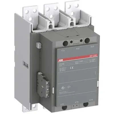
ABB AF1250-30-11-69 Block Contactor - UL/CSA 1000V
Part Number: 1SFL647001R6911
Quick Summary
AF1250-30-11-69 Block Contactor is a three-pole motor-switching device for heavy industrial applications. In real-world panels, voltage swings and surges can trigger unwanted trips, but this unit's wide control voltage range helps maintain consistent operation. It carries CE, UL/CSA, and UKCA certifications, and features integrated surge protection along with robust main circuit current ratings. The AF technology enables a broad input window (48–130 V AC or DC), reducing panel energy consumption and easing coordination in unstable networks. With add-on auxiliary contact blocks and a block-design for easy expansion, this solution scales from small to large motor control tasks while preserving reliability and safety.
Product Information
Extended Description
1SFL647001R6911 ABB: The AF1250-30-11-69 is a 3 pole - 1000 V IEC or 600 V UL contactor with pre-mounted auxiliary contacts and Main Circuit Bars, switching power circuits up to 1260 A (AC-1) or 1210 A UL general use. Thanks to the AF technology, the contactor has a wide control voltage range (48-130 V 50/60 Hz and DC), managing large control voltage variations, reducing panel energy consumptions and ensuring distinct operations in unstable networks. Furthermore, surge protection is built-in, offering a compact solution. AF contactors have a block type design, can be easily extended with add-on auxiliary contact blocks and an additional wide range of accessories.
Minimum Order Quantity
1 piece
Customs Tariff Number
85364900
Data Sheet, Technical Information
1SBC100214C0202 - Main catalog Motor protection and control Manual motor starters, contactors and overload relays (PDF) - Edition 2024
Data Sheet, Technical Information (Part 2)
Contactors and Overload relays guide
Instructions and Manuals
1SFC380023-en
CAD Dimensional Drawing
Information - 2D and 3D files for CAD systems
Product Net Width
210 mm
Product Net Depth / Length
242 mm
Product Net Height
344 mm
Product Net Weight
14.6 kg
Number of Main Contacts NO
3
Number of Main Contacts NC
0
Number of Auxiliary Contacts NO
1
Number of Auxiliary Contacts NC
1
Number of Poles
3P
Rated Operational Voltage
Main Circuit 1000 V
Rated Frequency (f)
Main Circuit 50 / 60 Hz
Conventional Free-air Thermal Current (Ith)
acc. to IEC 60947-4-1, Open Contactors Θ = 40 °C 1050 A
Rated Operational Current AC-1 (Ie)
(1000 V) 40 °C 1260 A | (1000 V) 55 °C 1040 A | (1000 V) 70 °C 875 A | (690 V) 40 °C 1260 A | (690 V) 55 °C 1040 A | (690 V) 70 °C 875 A
Rated Operational Current DC-1 (Ie)
(220 V) 3 Poles in Series, 40 °C 1250 A | (600 V) 3 Poles in Series, 40 °C 1250 A | (850 V) 3 Poles in Series, 40 °C 1250 A
Rated Operational Current DC-3 (Ie)
(220 V) 3 Poles in Series, 40 °C 1250 A | (600 V) 3 Poles in Series, 40 °C 1250 A | (850 V) 3 Poles in Series, 40 °C 1250 A
Rated Operational Current DC-5 (Ie)
(220 V) 3 Poles in Series, 40 °C 1250 A | (600 V) 3 Poles in Series, 40 °C 1250 A | (850 V) 3 Poles in Series, 40 °C 1250 A
Rated Breaking Capacity AC-3
8 x Ie AC-3
Rated Making Capacity AC-3
10 x Ie AC-3
Rated Short-time Withstand Current Low Voltage (Icw)
at 40 °C Ambient Temp, in Free Air, from a Cold State 10 s 7200 A | at 40 °C Ambient Temp, in Free Air, from a Cold State 15 min 1500 A | at 40 °C Ambient Temp, in Free Air, from a Cold State 1 min 4000 A | at 40 °C Ambient Temp, in Free Air, from a Cold State 1 s 8000 A | at 40 °C Ambient Temp, in Free Air, from a Cold State 30 s 5200 A
Maximum Breaking Capacity
cos phi=0.45 (cos phi=0.35 for Ie > 100 A) at 440 V 7500 A | cos phi=0.45 (cos phi=0.35 for Ie > 100 A) at 690 V 7000 A
Rated Insulation Voltage (Ui)
acc. to IEC 60947-4-1 and VDE 0110 (Gr. C) 1000 V | acc. to UL/CSA 600 V
Rated Impulse Withstand Voltage (Uimp)
Main Circuit 8 kV
Maximum Electrical Switching Frequency
(AC-1) 300 cycles per hour
Mechanical Durability
0.5 million
Maximum Mechanical Switching Frequency
300 cycles per hour
Coil Operating Limits
(acc. to IEC 60947-4-1) 0.85 x Uc Min. ... 1.1 x Uc Max. (at θ ≤ 70 °C)
Rated Control Circuit Voltage (Uc)
50 Hz 48 ... 130 V | 60 Hz 48 ... 130 V | DC Operation 48 ... 130 V
Coil Consumption
Holding at Max. Rated Control Circuit Voltage 50 Hz 12 V·A | Holding at Max. Rated Control Circuit Voltage 60 Hz 12 V·A | Holding at Max. Rated Control Circuit Voltage DC 5 V·A | Pull-in at Max. Rated Control Circuit Voltage 50 Hz 1100 V·A | Pull-in at Max. Rated Control Circuit Voltage 60 Hz 1100 V·A | Pull-in at Max. Rated Control Circuit Voltage DC 1020 V·A
Power Loss
at Rated Operating Conditions per Pole 80 W
Operate Time
Between Coil De-energization and NC Contact Closing 50 ... 70 ms | Between Coil De-energization and NO Contact Opening 53 ... 73 ms | Between Coil Energization and NC Contact Opening 45 ... 115 ms | Between Coil Energization and NO Contact Closing 50 ... 120 ms
Connecting Capacity Main Circuit
Bar 50 mm²
Connecting Capacity Auxiliary Circuit
Flexible with Ferrule 2x 0.75 ... 2.5 mm² | Flexible with Insulated Ferrule 2x 0.75 ... 2.5 mm² | Flexible 2x0.75 ... 2.5 mm² | Solid 2 x 1 ... 4 mm² | Stranded 1 x 1 .... 4 mm²
Connecting Capacity
Bar 50 mm²
Degree of Protection
acc. to IEC 60529, IEC 60947-1, EN 60529 Coil Terminals IP20 | acc. to IEC 60529, IEC 60947-1, EN 60529 Main Terminals IP00
Connecting Terminals (delivered in open position) Main Poles
M 3.5 (+,-) pozidriv 2 screw with cable clamp
Tightening Torque
Cable Lug 45 N·m
Terminal Type
Main Circuit: Bars
Product Name
Block Contactor
Horsepower Rating NEMA
(230 V AC) Three Phase 300 Hp | (460 V AC) Three Phase 600 Hp | (575 V AC) Three Phase 600 Hp
Maximum Operating Voltage UL/CSA
Main Circuit 1000 V
General Use Rating UL/CSA
(1000 V AC) 1210 A
Ambient Air Temperature
Close to Contactor Fitted with Thermal O/L Relay (0.85 ... 1.1 Uc) -25 ... 50 °C | Close to Contactor without Thermal O/L Relay (0.85 ... 1.1 Uc) -40 ... 70 °C | Close to Contactor for Storage -40 ... 70 °C
Maximum Operating Altitude Permissible
Without Derating 3000 m
Resistance to Shock acc. to IEC 60068-2-27
Shock Direction: A 5 g | Shock Direction: B1 5 g | Shock Direction: B2 5 g | Shock Direction: C1 5 g | Shock Direction: C2 5 g
Conflict Minerals Reporting Template (CMRT)
CMRT - Conflict Minerals Reporting Template
REACH Declaration
REACH - Letter of Confirmation for block contactors, contactor relays, installation contactors, mini contactors, mini contactor relays, thermal overload relays, electronic overload relays and related accessories
RoHS Information
RoHS II declaration for block contactors, installation contactors, mini contactors, mini contactor relays, thermal overload relays, electronic overload relays and related accessories
RoHS Status
Following EU Directive 2011/65/EU and Amendment 2015/863 July 22, 2019
Toxic Substances Control Act - TSCA
Toxic Substances Control Act (TSCA) declaration for Contactors
WEEE B2C / B2B
Business To Business
WEEE Category
5. Small Equipment (No External Dimension More Than 50 cm)
End Of Life Disassembling Instructions
End-of-life instruction - AF(S)580(B)-**;AF(S)750(B)-**; AF750N7; AF1250(B)-**
Environmental Product Declaration - EPD
Environmental Product Declaration AF(S)580(F)(N), AF(S)750(F)(N), AF1250 (SE) Contactors
ABS Certificate
ABS Certificate, Contactor, AF400...AF2050 (Sweden)
BV Certificate
BV Certificate, Contactor, AF400 ... AF2850
CB Certificate
SE-82865
CCS Certificate
CCS Certificate, Contactor, AF116 to AF2850 (Sweden)
CQC Certificate
CQC Certificate, Contactor, AF1250-30-*-*, Made in Sweden | CQC Certificate, Contactor, AF1250, Made in China
Declaration of Conformity - CCC
CCC Declaration of Conformity, Contactor, AF1250-30-*-*, Made in Sweden | CCC Declaration of Conformity, Contactor, AF1250, Made in China
Declaration of Conformity - CE
CE Declaration of Conformity - Contactor - AF400...AF2850
Declaration of Conformity - UKCA
UK Declaration of Conformity - Contactors >100A
DNV GL Certificate
DNV Certificate, Contactor, AF400...AF2850
EAC Certificate
9AKK107046A8618
LR Certificate
Lloyds register Certificate, Contactor, AF400...AF2850
PRS Certificate
PRS Certificate - AF116...AF1650
RINA Certificate
RINA Certificate, AF95, AF110, AF145, AF185, AF210, AF260, AF300, AF400, AF460, AF580, AF750, AF1250, AF1350, AF1650, AF2050, AF2650, AF116, AF140, AF146, AF190, AF205, AF265, AF305, AF370
RMRS Certificate
9AKK107045A6978
UL Certificate
cULus Certificate, Contactor, AF1250
UL Listing Card
UL_E73397
Package Level 1 Units
box 1 piece
Package Level 1 Width
280 mm
Package Level 1 Depth / Length
375 mm
Package Level 1 Height
310 mm
Package Level 1 Gross Weight
16 kg
Package Level 1 EAN
7320500355077
Object Classification Code
Q
ETIM 7
EC000066 - Power contactor, AC switching
ETIM 8
EC000066 - Power contactor, AC switching
ETIM 9
EC000066 - Power contactor, AC switching
eClass
V11.0 : 27371003
UNSPSC
39121529
IDEA Granular Category Code (IGCC)
4758 >> Iec Contactors
E-Number (Norway)
4115381
E-Number (Sweden)
4115381
Feature: Wide control voltage range of 48–130 V AC/DC. Business Impact: Enables reliable coil operation across fluctuating mains, reducing nuisance trips and panel wear. Application: Ideal for motor control panels in processing lines and pumping applications in environments with variable supply. Feature: Built-in surge protection. Business Impact: Protects the coil and downstream circuitry from transient spikes, lowering downtime and maintenance costs. Application: suitable for automation panels near heavy motors and variable loads. Feature: AF block-type design with expandability via auxiliary contact blocks. Business Impact: Scales control circuitry without complex rewiring, accelerating installation and upgrades. Application: large conveyors and multi-motor drives needing modular control. Feature: High rated currents (Ie up to 1260 A AC-1 at 1000 V; 1250 A DC- rating). Business Impact: Supports large-motor startups and high-load switching, reducing device count and improving reliability. Application: conveyors, pumps, and processing equipment. Feature: Main circuit bars and flexible auxiliary connections (50 mm² main, 2x0.75–2.5 mm² auxiliary). Business Impact: Simplifies wiring, improves terminal torque consistency, and speeds panel assembly. Application: panel builders and OEMs seeking robust, scalable power distribution. Feature: Robust certifications and environmental resilience (CE, UL/CSA, UKCA; IP20 coil terminals; 3000 m altitude allowance). Business Impact: Compliance across global markets with predictable procurement and reduced risk. Application: multinational manufacturing environments requiring cross-border approvals.
Get a Quick Quote for a ABB 1SFL647001R6911
Chat with us on WhatsApp - fast responses guaranteed
Need to speak with someone? We'll call you back within 2 hours during business hours
Interested in ABB 1SFL647001R6911?
Enquire Now
FAQs
Install the 3P main contacts with 50 mm² cables and secure coil terminals with IP20 protection. Use the M 3.5 (+,-) Pozidriv screws and cable clamp for secure connections; tighten cable lugs to 45 N·m. Ensure panel clearance and ventilation to maintain thermal performance at 40–70 °C ambient conditions.
The wide 48–130 V control range reduces control-voltage mismatches and energy waste, while integrated surge protection lowers transient-related losses. Coil consumption figures show lower holding currents at maximum rated voltage, contributing to overall panel efficiency, especially in systems with frequent cycling and varying load profiles.
Yes. It supports high currents with Ie up to 1260 A AC-1 at 40 °C and 1250 A DC-1/ DC-3/ DC-5 in various voltage configurations. It also offers strong short-time withstand and making/breaking capacities (AC-3), making it well-suited for demanding motor-start and stop cycles found in conveyors and pumps.
The AF1250-30-11-69 carries CE and UL/CSA declarations, plus UKCA and CB/CCC certifications in various markets. It also aligns with RoHS, REACH, and EAC requirements, supporting global procurement and reducing regulatory risk for multinational manufacturing.
Leverage the 50 mm² main-circuit bus connections and modular auxiliary blocks to minimize wiring complexity. Use the documented torque (45 N·m for lugs) and standard terminal types to speed commissioning, simplify spares planning, and extend service life through reduced contact wear and robust thermal management in multi-motor installations.