ABB GJL1213009R8101 Mini Contactor - IEC/EN 60947-4-1
Part Number: GJL1213009R8101
Quick Summary
The ABB Mini Contactor GJL1213009R8101 provides reliable switching for single- and three-phase loads in industrial control panels. Many engineers struggle with limited panel space and high coil energy requirements, making compact, PLC-friendly devices essential. It carries CE and UL/CSA registrations and IP20-rated terminals, ensuring safety and conformity across regional standards. In addition to core reliability, this solution delivers easy DIN-rail mounting, soldering-pin terminations, and clear switch-position indication, translating to reduced wiring effort and faster commissioning. For automation projects, it offers a compact, energy-efficient option that scales from simple control circuits to more demanding applications in commercial and industrial environments.
Product Information
Extended Description
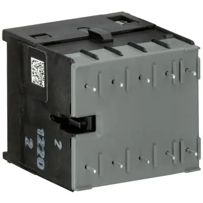
GJL1213009R8101 ABB: The BC6-30-10-P mini contactor is a compact 3 pole contactor with 1 auxiliary contact and soldering pins. They are ideally suited for applications where reliability is a must and space is at a premium. Mini contactors are used in residential buldings, commercial buildings and industrial applications for the control of single or three-phase loads up to 4 kW (AC-3) and 12 A (AC-1) or switching of control signals. Due to the low coil consumption, this device can be directly controlled by a PLC. Further features are the noiseless and hum-free coil and a switch position indication.
Minimum Order Quantity
1 piece
Customs Tariff Number
85365080
Data Sheet, Technical Information
1SBC100214C0202 - Main catalog Motor protection and control Manual motor starters, contactors and overload relays (PDF) - Edition 2024
Instructions and Manuals
2CDC102047M6801
CAD Dimensional Drawing
Information - 2D and 3D files for CAD systems
Dimension Diagram
Dimension Drawing - B6 / BC6 / B7 / BC7 / K6 / KC6 (-P)
Product Net Width
47.5 mm
Product Net Depth / Length
47.7 mm
Product Net Height
45.2 mm
Product Net Weight
0.17 kg
Number of Main Contacts NO
3
Number of Main Contacts NC
0
Number of Auxiliary Contacts NO
1
Number of Auxiliary Contacts NC
0
Number of Poles
3P
Standards
IEC/EN 60947-1 | IEC/EN 60947-4-1 | IEC/EN 60947-5-1 | UL 60947-1 | UL 60947-4-1 | IEC 60335-2-40 A2L
Rated Operational Voltage
Auxiliary Circuit 690 V AC | Auxiliary Circuit 250 V DC | Main Circuit 690 V AC | Main Circuit 220 V DC
Rated Frequency (f)
Control Circuit DC | Main Circuit 60 Hz | Main Circuit 50 Hz | Main Circuit DC
Conventional Free-air Thermal Current (Ith)
Main Circuit 12 A
Rated Operational Current AC-1 (Ie)
(220 / 240 V) 40 °C 12 A | (220 / 240 V) 55 °C 12 A | (380 / 440 V) 40 °C 12 A | (380 / 440 V) 55 °C 12 A | (690 V) 40 °C 6 A | (690 V) 55 °C 6 A
Rated Operational Current AC-3 (Ie)
(230 V) 55°C 9 A | (400 V) 55 °C 9 A | (500 V) 55 °C 6.5 A | (690 V) NO 55°C 3.5 A
Rated Operational Current AC-15 (Ie)
(24 V) 4 A | (120 V) 4 A | (500 V) 2 A | (220 / 240 V) 4 A | (380 / 400 V) 3 A
Rated Operational Current DC-13 (Ie)
(24 V) 2.5 A | (110 V) 0.7 A | (220 / 240 V) 0.4 A
Rated Operational Power AC-3 (Pe)
(230 V) Three Phase 2.2 kW | (400 V) Three Phase 4 kW | (500 V) Three Phase 4 kW | (690 V) Three Phase, NO 3 kW
Rated Breaking Capacity AC-3
8 x Ie / AC-3
Rated Making Capacity AC-3
10 x Ie / AC-3
Rated Short-time Withstand Current Low Voltage (Icw)
at 40 °C Ambient Temp, in Free Air, from a Cold State 10 s 64 A
Rated Insulation Voltage (Ui)
690 V | acc. to UL/CSA 600 V
Rated Impulse Withstand Voltage (Uimp)
Auxiliary Circuit 6 kV | Main Circuit 6 kV
Maximum Electrical Switching Frequency
(AC-1) 300 cycles per hour | (AC-15) 600 cycles per hour | (AC-3) 600 cycles per hour | (DC-1) 600 cycles per hour | (DC-13) 600 cycles per hour | (DC-3) 600 cycles per hour
Mechanical Durability
Nr. Operations 10000000 cycle
Minimum Switching Capacity
Auxiliary Circuit 17 V | Auxiliary Circuit 5 mA
Coil Operating Limits
(acc. to IEC 60947-4-1) for DC supply 0.85 ... 1.1 x Uc (at θ ≤ 55 °C)
Rated Control Circuit Voltage (Uc)
24 V DC
Coil Consumption
Average Holding Value DC 1.4 W | Average Pull-in Value DC 1.4 W
Power Loss
at Rated Operating Conditions AC-1 per Pole 1 W
Mounting on DIN Rail
TH35-15 (35 x 15 mm Mounting Rail) acc. to IEC 60715 | TH35-7.5 (35 x 7.5 mm Mounting Rail) acc. to IEC 60715
Degree of Protection
Auxiliary Circuit Terminals IP20 | Control Circuit Terminals IP20 | Main Circuit Terminals IP20
Terminal Type
Soldering Pins
Mini Contactor Type
Interface Mini Contactor
Product Name
Mini Contactor
Remarks
No CA6 or CAF6 mountable
Maximum Operating Voltage UL/CSA
Main Circuit 600 V AC
General Use Rating UL/CSA
(300 V AC) 8 A
Horsepower Rating UL/CSA
(115 V AC) Single Phase 0.25 Hp | (200 V AC) Three Phase 1 Hp | (220 ... 240 V AC) Three Phase 2 Hp | (230 V AC) Single Phase 0.5 Hp | (440 ... 480 V AC) Three Phase 3 Hp | (550 ... 600 V AC) Three Phase 1 Hp
Contact Rating UL/CSA
A600
Full Load Amps Motor Use
(115 V AC) Single Phase 5.8 A | (200 V AC) Three Phase 4.8 A | (220 ... 240 V AC) Three Phase 6.8 A | (230 V AC) Single Phase 4.9 A | (440 ... 480 V AC) Three Phase 4.8 A | (550 ... 600 V AC) Three Phase 1.7 A
Ambient Air Temperature
Operation -20 ... +55 °C | Storage -40 ... +80 °C
Maximum Operating Altitude Permissible
2000 m
Resistance to Shock acc. to IEC 60068-2-27
11 ms Pulse 15g
Resistance to Vibrations
5g 5 ... 150 Hz
Conflict Minerals Reporting Template (CMRT)
CMRT - Conflict Minerals Reporting Template
REACH Declaration
REACH - Letter of Confirmation for block contactors, contactor relays, installation contactors, mini contactors, mini contactor relays, thermal overload relays, electronic overload relays and related accessories
RoHS Information
RoHS II declaration for block contactors, installation contactors, mini contactors, mini contactor relays, thermal overload relays, electronic overload relays and related accessories
RoHS Status
Following EU Directive 2011/65/EU and Amendment 2015/863 July 22, 2019
Toxic Substances Control Act - TSCA
Toxic Substances Control Act (TSCA) declaration for Contactors
WEEE B2C / B2B
Business To Business
WEEE Category
5. Small Equipment (No External Dimension More Than 50 cm)
End Of Life Disassembling Instructions
End Of Life Instruction B(C)6-P, B(C)7-P, K(C)6-P, VB(C)6-P, VB(C)7-P
Environmental Product Declaration - EPD
Environmental Product Declaration PEP B(C)6, B(C)7 (EN)
A2L Certificate – IEC
A2L Certificate - B6-, B7-, K6- series, CA6, CAF6 - Mini Contactor
BV Certificate
BV Certificate - ESB24, ESB40, ESB63, EH04, B6, B7, EH04 - Installation Contactor
CB Certificate
CB Certificate - B6, BC6, VB6, VBC6, B7, BC7, VB7, VBC7 - Mini Contactor
CQC Certificate
CQC Certificate, AC Contactor, B6,BC6,B7,BC7,VB6,VBC6,VB7,VBC7, Made in Germany
cURus Certificate
cUL_E191658
Declaration of Conformity - CCC
CCC Declaration of Conformity, AC Contactor, B6,BC6,B7,BC7,VB6,VBC6,VB7,VBC7, Made in Germany
Declaration of Conformity - CE
EU Declaration of Conformity - B6, B7, K6, VB6, VB7, TBC7, TKC6 - Mini Contactor
Declaration of Conformity - UKCA
UK Declaration of Conformity - B6, B7, K6, VB6, VB7, TBC7, TKC6 - Mini Contactor
DNV GL Certificate
DNV Certificate - B6, B7 - Mini Contactor
EAC Certificate
EAC Certificate - B6, BC6, B6S, VB6,B7, BC7, B7D, B7S, VB7, TBC7, ESB24, EN24, ESB40, EN40, ESB63 - Contactors
KC Certificate
KC Certificate - B6, B7
LR Certificate
LR Certificate - B6, B7 - Mini Contactor
RMRS Certificate
RMRS Certificate - B6, BC6, B7, BC7, VB6, VBC6, VB7, VBC7 - Mini Contactor
Package Level 1 Units
box 10 piece
Package Level 1 Width
108 mm
Package Level 1 Depth / Length
247 mm
Package Level 1 Height
69 mm
Package Level 1 Gross Weight
1.775 kg
Package Level 1 EAN
4013614415234
Object Classification Code
Q
ETIM 7
EC000066 - Power contactor, AC switching
ETIM 8
EC000066 - Power contactor, AC switching
ETIM 9
EC000066 - Power contactor, AC switching
eClass
V11.0 : 27371003
UNSPSC
39121529
IDEA Granular Category Code (IGCC)
4763 >> Power contactor, DC switching
Feature: 3-pole configuration with 3 NO main contacts and 1 NO auxiliary contact. Benefit: Increased control capability in a single device, enabling compact panels and fewer components, which reduces wiring complexity and installation time in PLC-driven systems. Application: Best suited for small-to-mid sized industrial loads and building automation where space is at a premium. Feature: 24 V DC coil with low coil consumption (1.4 W holding / 1.4 W pull-in). Benefit: Lower energy draw reduces heat in control cabinets and simplifies power supply design, improving overall system efficiency. Application: Direct PLC interfacing for reliable, fast switching without external drivers. Feature: Soldering-pin terminals and 47.5 mm width with 47.7 mm depth and 45.2 mm height. Benefit: Easy panel wiring and compact footprint fit in tight control cabinets, cutting board space and material costs. Application: Ideal for DIN rail installations in modern automation panels. Feature: Rated insulation voltage up to 690 V and AC-3 power switching up to 4 kW. Benefit: Broad compatibility with standard industrial motors and loads, reducing part variety and inventory. Application: Motor control and signaling circuits in manufacturing lines. Feature: DIN rail mounting (TH35-15 and TH35-7.5) and IP20 protection. Benefit: Quick, secure installation with robust protection against environmental ingress in typical indoor environments. Application: Panel builders and system integrators seeking dependable, serviceable components. Feature: High mechanical durability (10,000,000 cycles) and UL/CSA, CE certifications. Benefit: Long operational life with predictable maintenance cycles and proven compliance for global deployments. Application: Heavy-use control systems in facilities and machinery where uptime matters.
Get a Quick Quote for a ABB GJL1213009R8101
Chat with us on WhatsApp - fast responses guaranteed
Need to speak with someone? We'll call you back within 2 hours during business hours
Interested in ABB GJL1213009R8101?
Enquire Now
FAQs
Mount the device on a TH35-15 or TH35-7.5 DIN rail in a clean, ventilated panel. Ensure the main and auxiliary terminals are accessible for soldering-pin connections, and verify IP20 protection after mounting. Tighten all terminals to the recommended torque and confirm the switch position indicator is visible during commissioning.
Coil voltage is 24 V DC with a coil consumption of 1.4 W (holding) and 1.4 W (pull-in). Main circuit voltage up to 690 V AC, with AC-3 rated operation of up to 4 kW at 400–690 V, and 12 A where applicable. Auxiliary contacts are 1 NO, suitable for control logic signaling.
Yes. The 24 V DC coil and compact 3P design are optimized for PLC direct drive, enabling reliable switching of loads up to the AC-3 rating while keeping wiring simple and minimizing coil energy demands in automated environments.
The device adheres to IEC/EN 60947-1, IEC/EN 60947-4-1, IEC/EN 60947-5-1, and UL 60947-1/60947-4-1, with CE and relevant RoHS/REACH declarations. It also features IP20 protection and is documented for safe installation in commercial and industrial applications.
Product net width is 47.5 mm, net depth 47.7 mm, and net height 45.2 mm, with a weight of 0.17 kg. These compact dimensions support tight panel layouts and reduce enclosure footprint while maintaining robust terminal access for soldering-pin connections.