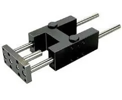
Norgren QA/8040/51/400 Guide Block - 40 mm Bore, 400 mm Stroke
Part Number: QA/8040/51/400
Quick Summary
QA/8040/51/400 guide block delivers precise linear motion for automated handling and positioning in manufacturing lines. In busy production cells, misalignment and wear can erode uptime and product quality; this cylinder mitigates those risks with a robust plain bearing design and reliable travel. The solution aligns with common standards such as CE conformity and available IP-rated configurations, supporting safe operation across regional markets. Designed for compact spaces and easy integration, it also offers CAD assets and installation documentation to accelerate design cycles and minimize commissioning time. For engineers and procurement teams, this combination delivers predictable performance, extended service intervals, and a clear path to scalable automation growth.
Product Information
Cylinder diameter
40 mm
Brand
IMI Norgren
Feature: 40 mm bore provides a compact footprint for tight installations. Business Impact: Enables smaller machine footprints and flexible layouts without compromising predictable actuation. Application: Ideal for compact automation cells and tabletop tooling. The 40 mm bore, when paired with the 400 mm stroke, supports longer travel in confined spaces. Feature: 400 mm stroke extends reach and reachability for pick-and-place tasks in flexible packaging lines, reducing the need for multiple actuators and lowering maintenance overhead. Business Impact: Improves throughput and lowers capital expenditure by consolidating functions into a single cylinder. Application: Assembly lines where longer travel is required without increasing system complexity. Feature: Plain bearing guide block design reduces friction, wear, and maintenance intervals. Business Impact: Extends service life under high-cycle conditions and lowers lubrication and replacement costs. Application: High-duty cycles in automated handling with consistent repeatability. Feature: Brand credibility and global support from IMI Norgren enhances parts availability and service responsiveness. Business Impact: Improves uptime through rapid spare parts access and local technical support. Application: Critical systems in factory automation that require reliable supplier backing. Feature: CAD assets and installation guides enable faster design-in and commissioning. Business Impact: Shortens engineering cycles, minimizes field errors, and accelerates time-to-first-action. Application: Engineers integrating pneumatic cylinders into control systems and mechanical assemblies.
Get a Quick Quote for a Norgren QA/8040/51/400
Chat with us on WhatsApp - fast responses guaranteed
Need to speak with someone? We'll call you back within 2 hours during business hours
Interested in Norgren QA/8040/51/400?
Enquire Now
FAQs
For compact cells, ensure mounting brackets and clevises align with standard patterns and the 40 mm bore fits available frame space. Use the CAD model to verify bolt hole spacing and stroke alignment before purchase. Consider the 400 mm travel in relation to cycle requirements and ensure end-of-stroke cushions are configured to avoid impact. Refer to the downloadable CAD and Installation Guide to plan mounting, fastener torque, and alignment procedures.
The plain bearing guide block reduces sliding friction, which minimizes heat buildup and wear during high-cycle operation. This translates to longer service intervals, lower lubricant consumption, and more consistent actuation force over time. In practice, you’ll experience steadier motion, reduced vibration, and easier maintenance scheduling, especially on lines with frequent start-stop sequences and tight position tolerances.
Yes. The 400 mm stroke provides extended reach for reach-and-place motions, while the 40 mm bore maintains a compact profile suitable for tight machine envelopes. The guide block design supports smooth, repeatable motion essential for precise placement, and the availability of CAD assets accelerates design integration. For high-speed lines, verify cycle time requirements against available air supply and control logic to optimize performance.
When integrating any automation actuator, review regional safety and compliance requirements for pneumatic components. Look for CE conformity for European applications and confirm any region-specific IP ratings or safety certifications applicable to your enclosure or machine. Always cross-check with your internal standards and consult the installation guide to ensure correct electrical and pneumatic connections, clearances, and environmental protections.
CAD models are available through the provided CAD download link, and an Installation Guide (PDF) is included in the downloads section. These resources enable accurate 3D integration and straightforward commissioning. Use the CAD files to verify mounting interfaces, create accurate bill-of-materials, and plan maintenance access, ensuring a smoother startup and ongoing reliability.