Norgren QA/8080/51/100 Guide Block - 80 mm Bore
Part Number: QA/8080/51/100
Quick Summary
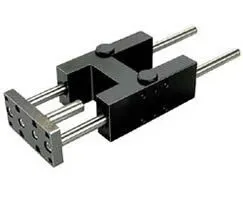
QA/8080/51/100 guide blocks provide precise linear guidance for pneumatic automation in compact machinery. Engineers often wrestle with wear, misalignment, and rising maintenance costs when using traditional plain bearings. Certification details are not listed in the provided data; in many industrial environments CE compliance and IP-rated variants are commonly sought, so verify the exact specs for your region. This guide block features an 80 mm bore and a 100 mm stroke, and it integrates with standard Norgren actuation systems, delivering reliable movement and easy installation. For OEMs and maintenance teams, the combination of compatibility, durability, and straightforward CAD-driven integration translates into reduced downtime and predictable performance.
Product Information
Cylinder diameter
80 mm
Brand
IMI Norgren
Feature: 80 mm bore and 100 mm stroke deliver a compact yet sturdy linear actuator path. Business Impact: Enables precise positioning in space-constrained machinery while maintaining repeatable motion; reduces cycle time and component wear. Application: Ideal for pick-and-place, alignment tasks, and slide-guided actuations in automation lines. Feature: Plain bearing style provides simple, robust guidance with fewer moving parts. Business Impact: Lower maintenance costs due to fewer wear-prone components and easier replacement parts supply; improved uptime in continuous operation. Application: Common in workshop automation and material-handling stations where reliability is mission-critical. Feature: CAD download and installation guidance are readily available. Business Impact: Speeds design validation and on-site installation, reducing engineering hours and installation risk. Application: Useful for OEMs integrating QA/8080/51/100 into custom assemblies or retrofit projects. Feature: Brand compatibility with IMI Norgren systems ensures interoperability. Business Impact: Streamlined spare parts planning and traceable compatibility across the line, minimizing integration friction. Application: Retrofit scenarios and system upgrades where existing Norgren components are in use. Feature: Space-efficient footprint supports dense automation layouts. Business Impact: Maximizes throughput in confined tool-racks and conveyor zones without compromising stroke, enabling smaller machines with the same performance expectations. Application: Assembly cells, picking stations, and automation racks where space is at a premium.
Get a Quick Quote for a Norgren QA/8080/51/100
Chat with us on WhatsApp - fast responses guaranteed
Need to speak with someone? We'll call you back within 2 hours during business hours
Interested in Norgren QA/8080/51/100?
Enquire Now
FAQs
To install the QA/8080/51/100 guide block, start by reviewing the Installation Guide PDF available in the product downloads. Ensure a clean mounting surface, align the block with the actuator's bore, and secure using appropriate fasteners per your machine’s torque specifications. Use the CAD file as a reference for exact mounting geometry, verify stroke clearance, and test run the system to confirm smooth, repeatable motion.
The core specs are an 80 mm cylinder bore and a 100 mm stroke, with a plain bearing guide block design. This configuration supports precise linear guidance suitable for pneumatic automation. The design emphasizes reliability in repeatable cycles and compatibility with standard Norgren actuation systems, helping maintain consistent cycle times and positioning accuracy.
The provided data does not specify a protective IP rating or sealing level for the QA/8080/51/100. For dusty or harsh environments, consider additional enclosure protection, proper alignment, and regular inspection of the plain bearings. If your application demands higher ingress protection, verify the exact specifications with the supplier or opt for a variant rated for your environmental conditions.
Maintenance focuses on monitoring wear in the bearing surfaces and ensuring smooth guidance. Regular visual checks for play or roughness, combined with periodic replacement of wear parts as per the OEM schedule, can extend service life. Use the CAD-guided maintenance guidelines and the Installation Guide to plan routine inspections aligned with your production cycles.
CAD models and the Installation Guide (PDF) are available in the product downloads section. Access the CAD file for accurate mounting geometry and use the Installation Guide to follow step-by-step assembly, alignment, and commissioning procedures. This supports faster design validation and error-free installation on your line.